
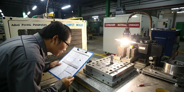
Are you seeing faint circles or stress marks on your finished plastic parts? These blemishes, known as ejector pin marks, can ruin the look of your product and lead to costly rejections. Ignoring them only creates more waste and frustration down the line. This guide will provide you with a clear, step-by-step diagnostic approach to identify the root cause and eliminate these defects for good, ensuring every part meets your quality standards.
Ejector-pin marks range from a small witness circle to a raised, recessed or distorted area that affects appearance or function. The mark may be caused by high ejection force, a part that is too soft, poor draft, uneven pin support, vacuum, packing stress, cooling imbalance, pin wear or a damaged cavity. Troubleshooting should begin with the pattern and timing of the mark rather than immediately reducing ejection speed.
Related CKMOLD resources: mold design, production injection molding, mold testing and validation.
To effectively troubleshoot ejector pin marks, you must adopt a systematic diagnostic approach. Start by checking the easiest-to-change processing parameters, such as reducing ejection speed and pressure, increasing cooling time, or lowering packing pressure. If the problem persists, move on to inspecting the mold itself. Check for proper ejector pin length, adequate draft angles, and polished core surfaces. Finally, evaluate your material selection to ensure it’s not too soft or prone to sticking. This methodical process helps you isolate the issue efficiently.
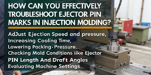
Fixing these marks isn’t just about tweaking a setting or two; it’s about understanding the ‘why’ behind the problem. This knowledge transforms you from a machine operator into a true molding expert. To build that expertise, we need to start with the fundamentals to ensure we’re all speaking the same language. Let’s begin with the component at the heart of the issue: the ejector pin itself.
The system-level sequence is explained in Ejector Pin Mark Root-Cause Analysis: Release Load, Timing and Support. This supporting guide concentrates on a troubleshooting sequence for visible pin marks.
What Is an Ejector Pin and What Is Its Role in Injection Molding?
You often hear the term “ejector pin” in molding, but do you fully grasp its critical function? Misunderstanding its purpose can make troubleshooting feel like guesswork. Without knowing how this simple component works, you might waste valuable time adjusting the wrong parameters.
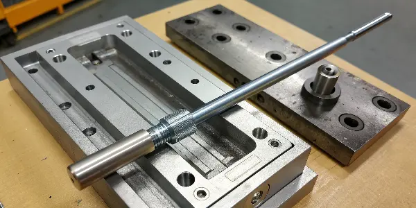
An ejector pin is a hardened steel rod located in the B-half (ejector side) of an injection mold. Its primary role is to push the solidified plastic part out of the mold cavity after the cooling cycle is complete. As the mold opens, the ejector system, which includes these pins, moves forward, applying a controlled force to the part. This action breaks the vacuum and overcomes any friction, ensuring a clean and damage-free release of the final product from the mold.
How Can You Identify Ejector Pin Marks on Your Molded Parts?
You’ve noticed a small imperfection on your finished part, but you’re not sure what it is. Is it a sink mark, a flow line, or something else entirely? Misidentifying the defect can send you down the wrong troubleshooting path, costing you time and material. Let’s clarify exactly what an ejector pin mark looks like so you can spot it immediately and begin the right corrective actions.
Ejector pin marks are surface defects on a plastic part that directly correspond to the location of the ejector pins in the mold. They typically appear as circular imprints, raised bumps, or white stress marks (blushing). In severe cases, the pin can even puncture the part, leaving a hole. You can identify them by turning the part over; the marks will be on the side that was in contact with the mold’s ejector half, reliably matching the ejector pin layout.
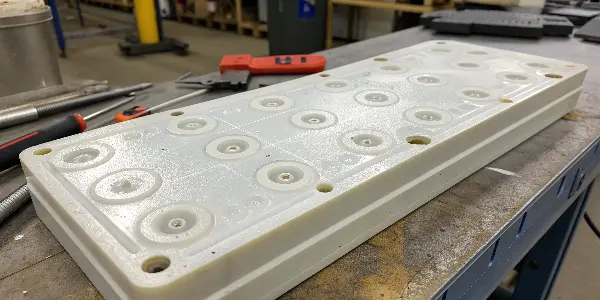
Identifying these marks correctly is the first step toward a real solution. Think of it like a doctor diagnosing an illness; you can’t prescribe the right medicine without knowing the exact problem. Ejector pin marks tell a specific story about what’s happening during the ejection phase of the molding cycle. They are a physical sign that too much force is being concentrated in a small area.
Here’s a simple way to confirm them:
- Look for a Pattern: The marks won’t be random. They will appear in a consistent pattern on every part, matching the layout of the pins in the mold.
- Feel the Surface: Run your finger over the suspected area. You can often feel a slight indentation or a raised surface where the pin made contact.
- Check for Stress: Look for a whitish discoloration around the mark, especially with more flexible or transparent plastics. This “blushing” is a clear sign of material being stressed beyond its limit.
- Compare to the Mold: If you have access to the mold design or the mold itself, you can directly compare the part’s marks to the locations of the ejector pins.
Once you can confidently say, “Yes, that’s an ejector pin mark,” you’ve moved from guessing to diagnosing. You’ve narrowed the problem down to the ejection system or the conditions preventing a clean release, which is exactly where we need to focus our attention next.
What Are the Primary Causes of Ejector Pin Marks?
You’ve correctly identified the ejector pin marks, but now you face the bigger question: why are they happening? Simply knowing the problem exists isn’t enough. If you start making random adjustments to the machine or mold, you could easily make things worse or create new issues. To fix the problem efficiently, you need to understand the common root causes.
The primary causes of ejector pin marks stem from excessive ejection force needed to release the part from the mold. This can be due to process settings like high packing pressure or insufficient cooling time, which makes the part stick. Mold design issues, such as inadequate draft angles, deep ribs, or a rough core surface, also increase adhesion. Finally, the ejector system itself, with pins that are too small or uneven in length, can concentrate force and create marks.
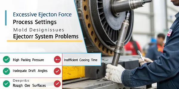
Think of it this way: the plastic part wants to stay in the mold, and the ejector pins have to push it out. If the part is “stuck” too tightly, the pins have to push harder. When that force exceeds what the still-warm plastic can handle, it leaves a mark. It’s like pushing your thumb into soft clay.
| Category | Specific Cause | How It Leads to Marks |
|---|---|---|
| Processing Parameters | High Packing/Holding Pressure | Over-packs the cavity, forcing the part to grip the core tightly. |
| Insufficient Cooling Time | The part is too soft and weak when the pins push against it. | |
| High Melt Temperature | Increases shrinkage, causing the part to grip the core more tightly. | |
| Mold Design & Condition | Inadequate Draft Angle | Vertical walls create high friction, acting like a brake during ejection. |
| Rough Surface Finish on Core | Microscopic undercuts on the mold surface grip the plastic. | |
| Insufficient Ejection Area | Ejector pins are too small or there are too few, concentrating force. | |
| Ejector System Issues | Uneven Pin Length | Some pins make contact before others, creating uneven force and stress. |
| High Ejection Speed/Force | The sudden impact of the pins stresses or punctures the part. |
How Do You Systematically Troubleshoot Ejector Pin Marks?
You know the potential causes, but where do you start? A chaotic, “try everything” approach is inefficient and can introduce new problems. To be effective, you need a logical, step-by-step process that starts with the easiest and cheapest adjustments first. This avoids costly mold modifications until you’ve ruled out simpler solutions.
A systematic troubleshooting process for ejector marks starts with process parameters, then moves to the mold, and finally the material. First, adjust the machine: lower packing pressure, increase cooling time, and reduce ejector speed. If that fails, inspect the mold: ensure pins are flush, apply mold release, and check for adequate draft. If the issue still isn’t resolved, it may point to a larger design problem requiring mold modification or a different material.
Here is a diagnostic checklist that you can follow, moving from the simplest to the most complex solutions.
Step 1: Process Parameter Adjustments (The Quick Fixes)
These are the first things you should check as they can be changed directly from the machine’s control panel.
- Reduce Packing/Holding Pressure: Lower the pressure in increments. This is often the primary culprit, as over-packing forces the part against the core.
- Increase Cooling Time: Give the part more time to harden so it can better resist the force of the ejector pins.
- Reduce Ejector Speed and Pressure: A slow, gentle push is generally better than a fast, sharp impact. Start low and only increase as needed.
- Lower Melt and Mold Temperatures: Hotter plastic shrinks more, causing it to grip the core tightly. Lowering temperatures can reduce this effect.
Step 2: Mold and Maintenance Checks (Requires Minor Intervention)
If process changes don’t work, it’s time to look at the mold itself.
- Check Ejector Pins: After a production run, are the pins reliably flush with the mold surface, or are some protruding or recessed? Uneven pins cause unbalanced force.
- Apply Mold Release Spray: As a temporary diagnostic tool, spray a light coat of mold release on the core side. If the marks disappear, it confirms the problem is related to sticking, likely due to a poor surface finish or lack of draft.
- Clean the Mold Cavity and Core: Residue and buildup can increase friction and cause parts to stick. A thorough cleaning is a simple but often overlooked step.
Step 3: Mold Design and Material Evaluation (The Deeper Fixes)
If the problem persists, it points to a more fundamental issue with the mold design or material.
- Verify Draft Angles: Check the part design. Are there adequate draft angles (typically 1-2 degrees) on all vertical faces?
- Increase Ejection Area: Can you use larger pins or add more pins in the problem areas to better distribute the ejection force?
- Evaluate Material Choice: Is the plastic you are using particularly “sticky” or soft? Sometimes, a material with better release properties can solve the issue.
By following this sequence, you ensure you’re addressing the most likely and easiest-to-fix causes first, making your troubleshooting process as efficient as possible.
Classify the Mark and Its Location
Record whether the mark is raised, recessed, shiny, cracked, surrounded by whitening or associated with sticking. Map it to pin diameter, core geometry, ribs, bosses, texture, parting line and flow direction. A cavity-side witness and a deflection mark have different causes.
Check Release Conditions
Confirm draft, texture depth, core polish, mold alignment, vacuum relief, undercuts, slide timing and cooling. A part that sticks to the core transfers excessive load to the ejector system. Improve release before changing pin force.
Review Ejection Support and Force
Small pins under a large area can push the part locally, while uneven pin height or poor plate guidance can tilt the part. Check pin size, distribution, sleeves, stripper plates, lifters, return pins, lubrication and alignment. Calculate force and support for the actual part.
Review Process and Part Stiffness
High packing, short cooling, high mold temperature, uneven shrinkage or a thick section can leave the part too soft or tightly gripped. Check part weight, gate freeze, cooling balance, ejection temperature, speed and robot handling.
Inspect Wear and Correct the Design
Bent or worn pins, damaged holes, flash, corrosion, burrs and poor polishing can create new marks. If the process is stable but the defect remains, consider larger or more numerous pins, sleeves, a stripper, a revised release direction or a replaceable insert.
Troubleshoot Ejector-Pin Marks in Injection Molding: Buyer Review Checklist
- Map mark shape and location to pins, cores, ribs, texture, flow and parting.
- Check draft, polish, undercuts, vacuum relief, slide timing, cooling and alignment.
- Review pin size, distribution, plate guidance, force, lubrication and support.
- Check packing, gate freeze, mold temperature, cooling, ejection temperature and handling.
- Inspect wear and make a design correction when process changes do not solve the cause.
FAQ
Why do ejector pins leave raised marks?
Local force can deform a warm or poorly supported part, especially when release resistance, packing stress or uneven pin support is high.
Can slower ejection remove pin marks?
It may reduce impact, but if the part is sticking or the pin layout is inadequate, speed alone will not remove the root cause.
Conclusion
Troubleshooting ejector pin marks doesn’t have to be a frustrating process of trial and error. By understanding the function of the ejector system, correctly identifying the defect, and knowing the primary causes, you can tackle the problem methodically. Start with process parameters, then inspect the mold, and you will isolate the root cause efficiently. This systematic approach will save you time, reduce scrap, and deliver the high-quality parts your customers expect.