
You’ve just received a batch of new plastic parts, but they’re marred by faint, unsightly lines where the plastic flowed together. These weld lines not only ruin the cosmetic appearance but can also create weak spots, leading to part failure and customer complaints. But what if you could anticipate and design these flaws out from the very beginning? Using smart design strategies and CAE analysis, eliminating weld lines is entirely possible.
Preventing visible weld lines begins before mold construction. The team should map how the polymer will flow around holes, inserts, ribs and gates, then decide whether the line can be moved to a hidden or noncritical area. If the line cannot be removed, thermal control, venting, material choice, texture and process settings can improve its appearance and strength, but every change should be checked against flash, warpage and cycle risk.
Related CKMOLD resources: DFM analysis, mold design, production injection molding.
To prevent weld lines, you must optimize part design, gate location, and injection molding parameters. Key strategies include using CAE mold flow analysis to predict plastic flow, positioning gates to ensure a single flow front, increasing melt and mold temperatures, and adjusting injection speed. Proper venting is also crucial to allow trapped air to escape, ensuring the plastic fronts merge seamlessly and create a strong bond. This proactive approach saves time and money on costly post-production fixes.
Weld lines are a frustrating problem, but they are just one of many challenges we face in injection molding. Understanding the root cause is the first step to a suitable part. Let’s start by looking at the bigger picture of common defects. By understanding these issues, you’ll be better equipped to troubleshoot not just weld lines, but any problem that comes your way. Ready to dive in and become a molding master?
Start with What Causes Weld Lines in Injection Molded Parts and Why They Matter to classify the flow-front event. The engineering question addressed here is appearance-led prevention for visible surfaces.
What are the most common injection molding defects?
Your production line is running, but the parts coming out have issues like sinks, burns, or warping. Each defective part is wasted money and time, hurting your bottom line and delaying your project timeline. Identifying the specific defect is half the battle.
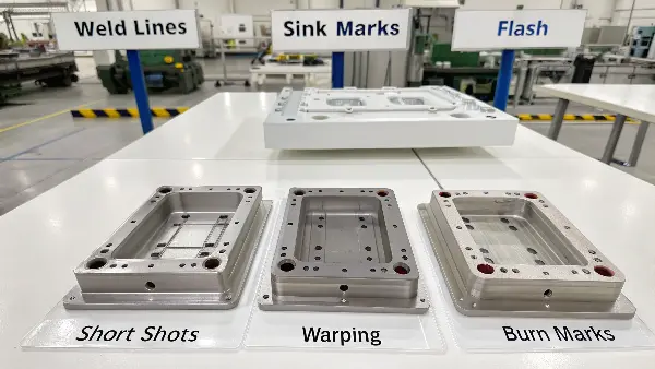
Common injection molding defects include weld lines, sink marks, flash, short shots, warping, and burn marks. Each is caused by different issues in the design, material, or process. For example, weld lines form where plastic flows meet, sink marks from uneven cooling, and warping from internal stresses. Recognizing these issues is the first step to producing high-quality, consistent parts that meet your exact specifications and avoid costly production errors.
To really master your production, you need to know these defects like the back of your hand. I’ve spent countless hours on the factory floor, and I can tell you that a quick diagnosis saves a ton of headaches.
Sink Marks
These are small depressions on the surface of a part. You’ll often find them in thicker sections. The cause is simple: the plastic on the outside cools and solidifies first, while the inside is still molten. As the inside plastic cools and shrinks, it pulls the surface inward, creating a sink. It’s a classic problem when you have parts with non-uniform wall thickness.
Flash
Flash is that thin, unwanted layer of plastic that appears at the edge of a part. It happens when the mold doesn’t seal reliably, and molten plastic seeps into the gaps. This can be due to a worn-out mold, not enough clamp pressure to hold the mold halves together, or even injecting the plastic too forcefully. It’s a sign that your mold or your machine settings need a check-up.
Short Shots
A short shot is exactly what it sounds like. The mold cavity doesn’t fill completely, so you end up with an incomplete part. Usually, this means the plastic solidified before it reached the end of the mold. The fix often involves increasing the injection pressure or temperature, or checking to see if your gates are too small and restricting flow.
How can you prevent weld lines in plastic parts?
You see that faint line on your finished part. You know it’s a weld line, a potential weak spot. Fixing this after the mold is made is expensive and time-consuming. You want to get it right from the start, but the interaction between part design, mold design, and machine settings feels complex and overwhelming. What if you could follow a clear, systematic approach to design these problems out before they ever happen?
Preventing weld lines requires a multi-faceted strategy focused on part design, mold layout, and process control. The best approach is proactive. Use CAE mold flow analysis early in the design stage to predict where weld lines will form. Then, adjust gate locations to move them to non-critical, less visible areas. Optimizing wall thickness for uniform flow and adding overflow wells can also effectively trap and hide these lines, ensuring a suitable part.
Over the years, I’ve learned that preventing weld lines isn’t about one magic fix. It’s about a combination of smart design and precise process control. You have power in two main areas: the design of the part itself and the way you run the injection molding machine.
Design and Mold Strategies
This is where you can make the biggest impact. Getting the design right from the start saves a world of trouble later on.
- CAE Mold Flow Simulation: This is your crystal ball. Before any steel is cut, mold flow software can simulate how the plastic will fill the mold. It shows you exactly where the flow fronts will meet and create weld lines. I use it on every project. It allows me to test different gate locations virtually and find the best spot to hide or eliminate the weld line.
- Gate Location: Where the plastic enters the mold is critical. The goal is to create a single, uninterrupted flow path for as long as possible. If you have holes or obstacles in your part, multiple gates can cause the plastic to split and rejoin, creating weld lines. A single gate, placed strategically, can often solve the problem.
- Part Geometry: Keep your wall thickness as uniform as possible. When plastic flows from a thick section into a thin one, it speeds up and can cause issues. Gradual transitions in thickness help maintain a consistent flow front. If you can’t avoid a hole in the part, consider adding an “overflow well” past the hole. This small pocket gives the weld line a place to form away from your main part geometry.
Process Parameter Optimization
Once the mold is built, you can still make adjustments on the machine.
| Parameter | Effect on Weld Lines | Recommended Action |
|---|---|---|
| Melt Temperature | Higher temps improve flowability, helping fronts merge better. | Increase temperature within the material’s recommended range. |
| Mold Temperature | A warmer mold keeps the plastic molten longer, allowing a stronger bond. | Increase the mold temperature to improve polymer chain diffusion. |
| Injection Speed | Faster injection reduces cooling time before fronts meet. | Increase speed, but watch for other defects like burn marks. |
| Venting | Proper vents allow trapped air and gas to escape. | Ensure vents are clean, correctly sized, and placed at the weld line location. |
What is the weld line strength factor and why does it matter?
You see a weld line on a part. It looks bad, sure, but you wonder if it’s just a cosmetic issue. Will it actually affect the performance of the part? You’re worried that this seemingly small flaw could cause the part to crack under stress, leading to product failure and damaging your company’s reputation. You need to know: how weak is this weld line, really?
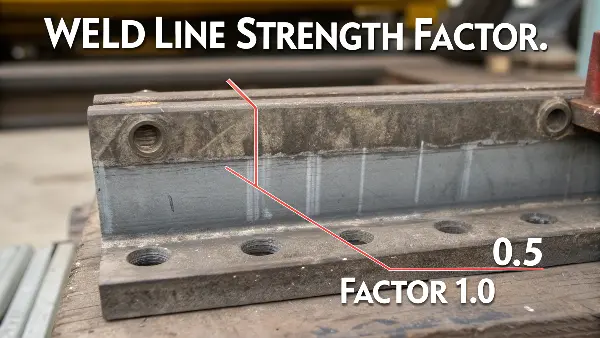
The weld line strength factor is a measure of how strong the weld line is compared to the rest of the material. A factor of 1.0 means it’s just as strong, while a factor of 0.5 means it has only 50% of the material’s nominal strength. This is critically important because weld lines can be significant structural weaknesses. For load-bearing parts, a low strength factor can lead directly to premature failure in the field, making it a crucial consideration in part design.
What Determines the Strength of a Weld Line?
The strength of a weld line depends entirely on how well the two separate melt fronts merge together when they meet. Think of it like trying to fuse two pieces of hot clay. If they are hot and you press them together firmly, they become one. If they’ve cooled down too much, they’ll just stick together weakly. For plastics, the key is the entanglement of long polymer chains across the interface.
Several factors influence this:
- Melt Temperature: Hotter plastic flows better and has more thermal energy. This allows the polymer chains from both fronts to move around and entangle with each other before they solidify. Higher melt temperature often leads to a stronger weld line.
- Meeting Angle: The angle at which the two flow fronts meet matters. A ‘head-on’ collision (a 180-degree meeting angle) creates a very distinct and often weak line. A merge where the flows meet at a shallow angle (less than 135 degrees) allows for better mixing and results in a stronger bond.
- Fillers and Fibers: If you’re using a plastic with fillers, like glass fibers, they can make weld lines even weaker. The fibers tend to align with the flow direction. At the weld line, they can end up oriented parallel to the line, but not crossing it. This means there are no fibers bridging the gap to add strength, which can reduce the strength factor dramatically.
How do you fix warpage in injection molding?
You’ve just molded a large, flat part. But when you take it out of the machine, it’s twisted and bent, like a potato chip. This warpage makes it impossible to assemble with other components. You’re losing time and material on every bad part, and your production schedule is at risk. You need to get these parts flat, but the cause isn’t immediately obvious.
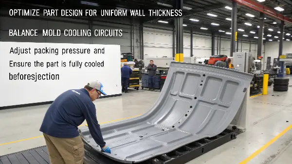
To fix warpage, you must address the root cause: non-uniform shrinkage. This is best achieved by optimizing part design, mold cooling, and processing parameters. Ensure uniform wall thickness in your part design. In the mold, balance the cooling circuit to prevent one area from cooling faster than another. Finally, adjust packing pressure and time on the machine to compensate for shrinkage, and check that the part is fully cooled before ejection.
Warpage is one of the trickiest defects because it’s caused by internal stresses you can’t see. The part looks fine in the mold, but as it cools, these hidden stresses pull and push the part into a new, distorted shape. It’s a battle against physics, but one you can win with the right knowledge.
Finding the Source of Uneven Shrinkage
Everything in injection molding shrinks as it cools. Warpage happens when one part of the component shrinks more than another. Your job is to figure out why.
- Part Design Issues: The number one cause A common observation is is non-uniform wall thickness. A thick section will take much longer to cool and will shrink more than a thin section next to it. This differential shrinkage creates stress and pulls the part out of shape. The golden rule is to keep walls as uniform as possible. If you must have thick sections, core them out to maintain uniformity.
- Mold Cooling Problems: Your mold is filled with cooling channels. If one side of the mold is running hotter or colder than the other, the part will cool unevenly. We once had a warping issue that we traced back to a single clogged cooling line. Ensuring your cooling circuit is balanced and providing consistent temperature across the entire part surface is absolutely essential.
Process Adjustments to Control Warpage
If your part and mold design are solid, you can fine-tune the process.
| Parameter | Impact on Warpage | Recommended Action |
|---|---|---|
| Packing Pressure | Higher packing pressure forces more material into the mold to compensate for shrinkage. | Increase packing pressure and time, but be careful not to create flash or overpack the part. |
| Melt Temperature | A higher melt temperature can lead to more overall shrinkage. | Try lowering the melt temperature slightly, as long as it doesn’t cause short shots. |
| Cooling Time | Ejecting the part too early while it’s still soft can cause it to warp. | Increase the cooling time to ensure the part is rigid and stable before it’s pushed out of the mold. |
Move the Line With Gate and Geometry Decisions
Gate location, fan or tab gates, flow leaders, overflow wells and controlled wall transitions can change where fronts meet. Sometimes moving an opening, changing a rib, adding a flow path or using a different parting strategy is more effective than changing machine settings.
Keep the Meeting Fronts Hot and Clean
A suitable melt and mold temperature can improve flow-front contact, while drying and residence control reduce splay or degradation. Injection speed may need to keep the front mobile, but faster filling can increase gas compression, so venting must be adequate.
Improve Venting at the Meeting Zone
Air trapped where fronts meet can create a pale, dark or weak line. Vent or overflow features at the appropriate destination can reduce gas pressure. Inspect the vent after trials because a blocked path may make the defect return.
Use Surface and Material Strategically
Texture can reduce visual contrast, but it should not be used to hide a structural issue. A different grade, colorant, filler or flow modifier may change the line, while also changing shrinkage, strength, tool wear and compliance. Validate the complete material choice.
Approve by Appearance and Function
Define critical cosmetic zones, viewing condition, line limit, weld-line strength, sealing and fatigue requirements. A line that looks better after a temperature increase is not a successful correction if it raises flash, degradation or dimensional variation.
Prevent Visible Weld Lines in Plastic Parts: Buyer Review Checklist
- Map weld lines early and decide whether gate, opening, rib or parting changes can relocate them.
- Control resin drying, residence, melt and mold temperature and fill speed.
- Add or correct venting and overflow at the actual flow-front meeting zone.
- Use texture or material changes only after checking strength, shrinkage, wear and compliance.
- Set separate visual and functional acceptance criteria and validate both.
FAQ
Can increasing injection speed hide a weld line?
It may reduce visible contrast by keeping fronts warmer, but it can also increase gas compression, flash or burn; validate the complete result.
Can texture eliminate a weld line?
Texture can reduce visual contrast, but it does not remove the interface or support strength; functional testing remains necessary.
Conclusion
Preventing defects like weld lines and warpage is not a matter of luck. It comes from a deep understanding of part design, mold functionality, and the injection molding process. By using tools like CAE analysis and systematically optimizing your designs and machine settings, you can turn these common frustrations into consistent, high-quality results. This proactive approach will generally save you time, reduce waste, and build trust with your customers.