
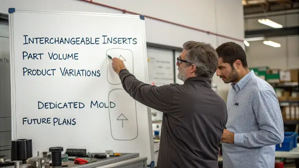
Interchangeable inserts can reduce duplicated tooling or repair scope when product variants share a stable mold envelope. They can also add interface, changeover, qualification and shared-base downtime cost. Compare both routes over the planned variant mix before claiming a saving.
Interchangeable core and cavity inserts allow a mold to carry replaceable geometry instead of making every product change a modification to the main mold block. Used correctly, inserts can support product variants, protect high-wear regions, speed up repairs and simplify future corrections. They also introduce alignment, sealing, cooling and spare-part decisions that must be engineered from the start.
Related CKMOLD resources: mold design services, mold repair or modification, multi-cavity molds.
A modular design needs a common base only where variants can share load paths, machine interfaces, actions, ejection, utilities and safe operating limits. Define insert boundaries, location, support, locking, shutoffs, cooling, handling, identification and requalification for each variant; flexibility and cost benefits must be demonstrated for the actual program.
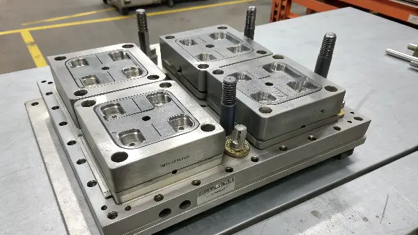
This all sounds great in theory, but putting it into practice requires careful attention to detail. You can’t just drop any insert into a mold base and expect it to work. There are specific design principles you need to follow to make sure everything fits reliably, runs efficiently, and lasts a long time.
How Should Inserts Be Located, Supported and Locked?
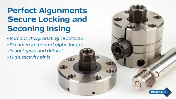
Location, support and locking are separate functions. A locator establishes repeatable position; a seating surface and backup steel carry molding load; locks or fasteners retain the insert and prevent separation or movement. Do not ask a dowel, bolt or taper to perform every function without a load-path check.
| Design question | Possible feature | Evidence to require |
|---|---|---|
| How is position established without over-constraint? | datum faces, dowels, keys, pilot or taper selected for geometry and service | datum scheme, fit/tolerance and repeated-installation results |
| Where does injection and clamp load go? | supported seating/backup faces near the load | contact check, deflection/flash result and steel condition |
| How are shutoffs protected? | interlocks and controlled contact separate from installation guidance | contact map, witness/flash criteria and wear inspection |
| How is the insert retained and serviced? | bolts, clamps or retainers with access and identification | fastener specification, torque/service method and safe removal plan |
Rankings such as “excellent precision” or “best for all sizes” are not meaningful without the insert size, load, tolerance, thermal condition and wear plan. Qualify alignment and sealing after repeated swaps and with accepted molded parts.
Standardize Interfaces Without Hiding Variant Risk
Cooling, ejection, sensors and actions can share base interfaces only when every insert variant remains within the approved thermal, mechanical and stroke envelope. A common connector or manifold reduces setup steps but does not make leaks or wrong connections impossible.
| Interface | Standardize | Requalify for each insert |
|---|---|---|
| cooling | ports, seals, manifold pattern and identification | flow, leak, pressure drop and surface-temperature balance |
| ejection | coupling plane and safe machine interface | stroke, contact, load, return and mark/distortion limits |
| sensors/actions | connector and signal naming | sequence, limits, fault response and safe recovery |
| process recipe | revision/selection control | fill, pack, cooling and part acceptance window |
Qualify changeover with a timed, documented study that includes shutdown, removal, inspection, installation, utilities, recipe verification, startup scrap and first accepted part. Do not publish universal “under five minutes” or manual-hose times without that project evidence.
When Do Interchangeable Inserts Beat Dedicated Tools?
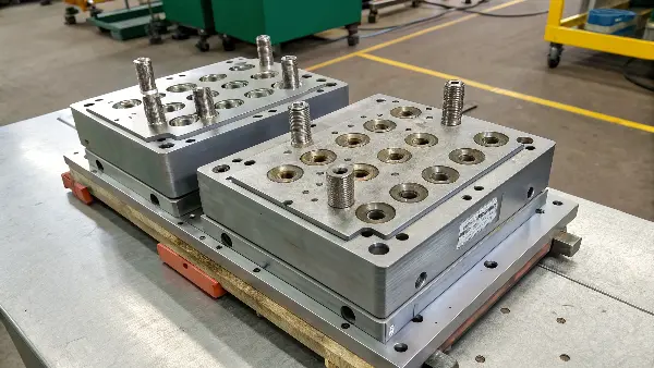
Use modular inserts when variants share a stable mold envelope and the savings from reused base systems exceed added interface, changeover, validation and scheduling cost. Dedicated tools may be preferable when demand overlaps, variants need very different cooling/actions, or changeover risk and shared-base downtime dominate.
Illustrative calculation—not a CKMOLD quotation: compare lifecycle cost for each route as tooling + variant inserts/tools + qualification + changeovers + startup scrap + maintenance + expected shared-base downtime. Divide by accepted parts only after applying each variant’s demand and yield. There is no universal $30,000/$70,000/$10,000 break-even.
DME’s public MUD modular tooling overview demonstrates the general interchangeable-base concept. It does not establish fit, cycle or economics for a particular product.
Define the Interchangeability Acceptance Record
For every insert, record revision, steel/condition, locating and locking features, shutoff/contact check, cooling-flow result, action/ejection sequence, approved recipe and first-off dimensions. After repeated swaps, recheck witness/flash, critical dimensions and connection wear. Interchangeability is demonstrated by repeatable installation and accepted parts—not by nominal insert dimensions alone.
Use Inserts Where Change or Wear Is Real
Good candidates include product-identifying geometry, high-wear gates or shutoffs, interchangeable variants, textured surfaces and areas likely to need correction. An insert added only to make the CAD look modular may increase cost and create another interface without a useful maintenance benefit.
Design Alignment and Shutoff Like a Precision Joint
Locating features, taper, keys, bolts, support and preload determine whether the insert returns to the same position. Parting-line contact and shutoff geometry must resist flash under cavity pressure. The insert should be supported against movement, not held only by a fastener.
Plan Cooling and Thermal Continuity
A replaceable insert can interrupt cooling or create a hot spot. Independent channels, thermal contact, copper-alloy solutions or controlled interface design may be needed. Cooling connections and sealing must allow removal without damaging the mold or contaminating the circuit.
Build a Spare and Revision Strategy
Each insert should have an identification mark, drawing revision, steel and heat-treatment record, inspection data and storage location. Spare inserts are valuable only when they are interchangeable in practice; dimensions, surface, hardness and fit must be verified before release.
Measure the Lifecycle Value
Compare the insert architecture with a conventional block by product variants, expected wear, repair time, downtime, spare cost, correction probability and future volume. The best case is a tool that can change or recover quickly without sacrificing part repeatability.
Interchangeable Core and Cavity Inserts: Buyer Review Checklist
- Use interchangeable inserts for real variants, wear, texture or correction risk—not as decoration.
- Design location, support, preload and shutoff contact to prevent movement and flash.
- Preserve thermal performance with independent cooling or suitable interface design.
- Document insert ID, revision, steel, heat treatment, inspection and spare storage.
- Compare downtime, repair speed, spare cost and repeatability over the mold lifecycle.
FAQ
Do interchangeable inserts generally reduce mold cost?
Not necessarily. They can reduce future correction or variant cost, but the initial structure, fitting, cooling and inspection add complexity.
Where are inserts most useful?
They are useful for product variants, high-wear areas, textures, gates, correction-prone features and parts that need quick maintenance recovery.
Conclusion
Interchangeable inserts create value when variants share a stable architecture and changeover, utilities, alignment, qualification and shared-base risk are engineered explicitly. Compare lifecycle cost and accepted capacity with dedicated tools, then prove repeatability through documented swaps and molded-part evidence.