
Related engineering resources: mold testing and validation | DFM analysis | prototype injection molding
Choose tests from the product’s actual failure risks and state how the prototype differs from production material, tooling and process. Material coupon tests and finished-part functional tests answer different questions; document sample state, quantity rationale, method and acceptance criteria before testing.
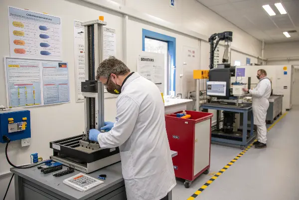
Illustrative laboratory scene; not a record of a CKMOLD test or certified facility.
Which Mechanical Tests Match the Prototype’s Failure Risks?
Select mechanical tests that represent the actual load path and failure mode. Tensile, compression, impact or flexural coupon data can inform material selection, while assembly, drop, fatigue or retention tests may be needed for the finished geometry.
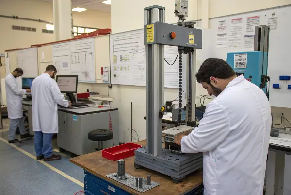
Illustrative equipment. Select the actual specimen, fixture and test method for the requirement.
Tensile and Compressive Strength: The Push and Pull
Tensile testing measures the response of a specimen to a controlled pulling load; report strength, stiffness and elongation with the material, specimen geometry, conditioning and test rate. ASTM D638 describes tensile-property testing of plastic specimens. A material result does not by itself establish the strength of a molded handle, weld line or fastener joint. Compression tests and finished-part load tests must likewise represent the relevant geometry and support conditions.
Impact and Flexural Strength: Surviving Shocks and Bends
Impact tests evaluate response to a rapid load under specified specimen, notch and temperature conditions. Use finished-assembly drop or impact tests when those represent the failure risk. Flexural testing measures bending response: ASTM D790 uses a supported specimen with three-point loading. Flexural stiffness and strength are not a demonstration of repeated living-hinge or snap-fit endurance; check cyclic strain, retention and damage on representative parts for that duty.
| Test | What it can establish | Application boundary |
|---|---|---|
| Tensile | Stress-strain response of the defined specimen | Finished joints and load paths still need geometry-specific verification. |
| Compression | Response to the specified compressive loading | Support, duration, temperature and possible buckling matter. |
| Impact | Response to a defined rapid loading event | Notch, orientation and temperature affect interpretation; assembly drops may be different. |
| Flexural | Stiffness and stress response under the defined bending method | Does not establish fatigue life or repeated hinge operation. |
How Do Environmental Factors Impact Your Prototype’s Performance?
Define temperature, moisture, UV and exposure duration from the intended service environment. An accelerated test needs a justified relationship to the release decision; passing it does not automatically prove the full service life.
Temperature Extremes: Thermal Cycling
Select hot and cold limits, dwell times, transition rate and cycle count from the intended environment and release decision. Check the complete assembly for dimensional change, cracking, seal leakage and retained function where relevant. Thermal cycling addresses repeated temperature change; heat aging addresses time at temperature. A short heat-deflection test is a different measurement: ASTM D648 explicitly limits using its data to predict elevated-temperature endurance. Do not substitute a heat-deflection value for a service-life demonstration.
Humidity and Moisture: Specify the Condition
For a moisture-sensitive grade, compare the dimensions and relevant mechanical or assembly performance at the specified conditioning state. Record temperature, relative humidity, exposure duration and measurement timing. Distinguish humid-air conditioning from immersion: choose the exposure that represents service, and use the resin supplier’s grade-specific conditioning guidance. A pass supports the tested conditions; it does not establish performance in every wet environment.
| Environmental Factor | Potential Negative Effect on Plastic | Recommended Test Protocol |
|---|---|---|
| High Temperature | Softening, deformation and loss of function under the actual load and duration. | Application-specific heat aging or loaded-part evaluation; HDT is a separate screening measurement. |
| Low Temperature | Increased brittleness, cracking. | Cold Temperature Impact Test |
| Temperature Swings | Cracking, warping due to expansion/contraction. | Thermal Cycling Test |
| High Humidity | Swelling, loss of mechanical properties. | Humidity Chamber / Water Immersion Test |
| UV Radiation (Sunlight) | Color fading, yellowing, embrittlement. | Accelerated UV Weathering Test |
Can Your Prototype Withstand Chemical Exposure and Assembly Stresses?
Select chemical and assembly checks from the actual service conditions. For chemical exposure, specify the fluid or cleaner, concentration, contact method, temperature, duration and mechanical stress, then inspect appearance and relevant dimensions or function. For assembly, use representative mating parts, fasteners and fixtures to check interference, tolerance stack-up and induced stress. No single exposure or fit check establishes every aspect of reliability.
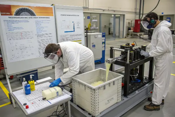
Illustrative chemical-testing scene; the written exposure conditions and acceptance method govern the test.
Chemical Resistance: More Than Just Acids
Relevant substances can include skin oils, lotions, cleaning products, lubricants or process residues. ASTM D543 distinguishes exposure methods and emphasizes the relationship between test and service conditions. Use unexposed controls and define the properties to compare before and after exposure. A brief wipe with one solvent cannot establish resistance to other cleaners or long-term immersion; combined chemical and mechanical stress may require a separate assessment.
Fit and Assembly: From CAD to Reality
Check assembly with representative mating parts, fasteners and seals. A single successful fit does not establish interchangeability across all tolerance combinations. During a fit and assembly analysis:
- Check Tolerances: Do all parts fit together without being too loose or too tight?
- Identify Interference: Are there any areas where parts collide or don’t align properly?
- Assess Assembly Stress: Does the act of snapping parts together or tightening screws create too much stress, potentially leading to future cracks?
| Test Category | Specific Test Example | What It Validates |
|---|---|---|
| Chemical Resistance | Defined isopropyl-alcohol formulation, contact method, duration, temperature and part stress, if relevant to the intended use. | Evidence for that exposure and acceptance criterion only; not a guarantee for all cleaning agents. |
| Chemical Resistance | Exposure to the specified service fluid at defined concentration, temperature, stress and duration. | Evaluates compatibility under the stated exposure; additional aging and functional confirmation may be required. |
| Fit & Assembly | Test assembly with mating parts and fasteners. | Demonstrates fit for the tested combination; use dimensional inspection and tolerance analysis to assess broader variation. |
| Fit & Assembly | Repeated assembly/disassembly cycles. | Checks retained function and damage after the specified cycle count, loads and conditioning; not unlimited joint life. |
How Do You Create a Comprehensive Functional Testing Plan?
Start with the end-use requirements and critical-to-quality characteristics, then connect each relevant failure mode to a verification method. Record the sample condition, quantity rationale, fixtures, equipment, procedure, acceptance limits and decision owner. State what a pass supports and which risks remain open. This makes results reviewable without claiming that a finite test plan proves all future performance.
Agree the test plan before relying on prototype results for tooling release. Record who approves the method, what decision each result supports and which findings require confirmation on production-representative molded parts.
When requirements are still qualitative, first translate customer needs into testable part specifications. A test method cannot resolve an undefined acceptance limit.
Step 1: Define End-Use and Critical-to-Quality (CTQ) Features
Before you can test anything, you have to know what you’re testing for. Start by writing down a detailed description of the product’s life.
- Environment: Will it be indoors or outdoors? Exposed to sunlight? Used in a high-humidity area?
- User Interaction: How will people handle it? Will it be dropped? Are there buttons to be pressed thousands of times?
- Mechanical Loads: What forces will it experience? Will it support weight? Does it need to contain pressure?
From this, you identify the CTQs—the features that absolutely must not fail. This could be the strength of a mounting tab, the seal of a gasket, or the clarity of a lens.
Step 2: Select Tests and Define Pass/Fail Criteria
For each CTQ, specify the test conditions and acceptance threshold from the product requirement. For a drop test, define height, orientation, surface, sample condition and post-test function rather than copying a generic one-meter example.
| Plan Component | Description | Example |
|---|---|---|
| Requirement | A high-level goal for the product. | The device housing must be durable enough for daily handling. |
| CTQ Feature | The specific feature that enables the requirement. | The snap-fit clips that hold the housing together. |
| Test Protocol | The specific test to validate the CTQ. | Illustrative plan format: assembly/disassembly cycles selected from the service requirement. |
| Pass/Fail Criteria | The objective measure for success. | Specify the required retention force, inspection conditions and permissible damage after the agreed cycle count. Values must come from the product requirement. |
Translate Requirements Into Testable Risks
List strength, stiffness, impact, fatigue, temperature, chemicals, moisture, sealing, wear, assembly, appearance and dimensional requirements. Rank risks by severity and uncertainty. Avoid testing a convenient property that is unrelated to the product’s likely failure mode.
Choose a Representative Prototype State
Record method, material, orientation, post-processing, conditioning, hardware and assembly. If the prototype is not production-representative, define a correlation or confirmation step with molded parts. Prototype results are evidence with a boundary, not a universal prediction.
Control Fixtures, Loads and Measurements
Use repeatable datums, realistic constraints, load rates, temperature, humidity, cycle count and inspection timing. A fixture can create an artificial stress concentration or mask a real one. Calibrate equipment and record raw observations, not only pass/fail.
Inspect Failure Mode and Variation
Capture cracks, pullout, creep, whitening, delamination, wear, leakage, distortion and cosmetic changes. Test enough samples to see variation and compare orientations or process conditions when relevant. The failure location often teaches more than the headline load.
Close the Correlation Loop
Use the result to adjust geometry, material, assembly, tooling or test method, then confirm the changed risk. Before release, show which prototype findings transferred to production and which were rechecked with molded parts, production-like tooling or environmental aging.
Validate Plastic Prototype Performance Before Production: Buyer Review Checklist
- Map requirements to likely failure modes, severity and uncertainty.
- Record prototype method, material, orientation, conditioning, hardware and limitations.
- Control fixtures, loads, rates, environment, datums, calibration and timing.
- Document failure location, variation, photos, raw observations and acceptance.
- Close the loop with DFM, material, tooling or production-representative confirmation.
Frequently Asked Questions
How many prototype samples are needed?
The number depends on risk, variation, test destructiveness and decision importance. Define a rationale rather than using a universal sample count.
Can prototype testing replace production validation?
It can reduce risk and guide design, but production-like parts and processes may still be needed for shrinkage, weld lines, material conditioning, tool variation and release evidence.
Conclusion
Use prototype testing to reduce defined risks and document remaining uncertainty. Before production approval, confirm which findings transfer to the molded material and process and repeat the tests that depend on production conditions.