

Specify an automotive mold’s locating ring from the approved receiving press interface and mold assembly. Confirm bore and engagement, nozzle/sprue alignment, operating temperature, handling and clamping before choosing a material, coating or tighter fit. The automotive application alone does not establish a need for a special ring.
Automotive tools may transfer between presses and plants, making a controlled mold-to-machine interface important. The locating ring helps repeatably center the stationary mold at the nozzle; gate balance, parting-line closure and assembly tolerances still depend on the rest of the tool and process.
A standard supplier ring can be suitable when it meets the approved press and mold drawings. Departures from standard components need a documented interface requirement and a verifiable acceptance method; mold weight, production volume or part tolerance alone does not justify an upgrade.
The locating ring seems like a simple part, just aligning the mold to the machine platen. But in the demanding world of automotive manufacturing, where molds can be massive and part quality is non-negotiable, this simple component takes on critical importance. Understanding these specific needs is key to reliable and efficient production.
What is a Locating Ring, Fundamentally?
During setup, verify the stationary mold’s position relative to the machine nozzle. Diagnose flash, part dimensions and internal mold-half alignment separately; those symptoms do not establish a locating-ring fault.
A locating ring is a fundamental mold component, a circular component of the material and hardness specified by its supplier mounted on the mold’s stationary side. Its precise outer diameter fits into a matching bore on the injection molding machine’s fixed platen, supporting repeatable initial alignment between the mold’s sprue bushing and the machine’s nozzle.
The ring’s locating diameter engages the specified platen bore during installation. Confirm the ring mounting and its relationship to the sprue-bushing/nozzle axis from the assembly drawing. Dedicated supports and clamps carry and secure the mold; do not force an incorrect ring into the bore. Investigate these interfaces separately when diagnosing a setup fault:
- Parting-line flash requires checks of clamp force, support, tool fit and process pressure. It should not be attributed to the locating ring without evidence of a related seating or interface problem.
- Cavity/core alignment and ejector positions are controlled by the mold and machine setup; the stationary locating ring alone does not establish those relationships.
- Mold Wear: Inspect shut-offs and guides independently. Their wear does not identify the locating ring as the cause without a demonstrated interface fault.
- Nozzle Issues: Poor alignment between the machine nozzle and sprue bushing can lead to leakage, material degradation, or difficulty filling the part.
-
Platen and seating check: Inspect the bore, seating surfaces and clamping/support arrangement for damage or unintended contact before approving installation.
Feature Description Consequence of Issue Function Align mold center to machine platen center Incorrect nozzle-to-sprue centering; mold-half alignment is separate Interface OD fits into platen counterbore Poor fit leads to sloppy alignment Mounting Bolted to top clamp plate, around sprue bushing Incorrect mounting causes errors Material Supplier-specified material and hardness Assess wear against the approved specification Purpose Repeatable installation and nozzle-interface positioning Verify the actual setup fault; part capability is separate What are the Common Types of Locating Rings Available?
Compare the standard component with any supplier-proposed alternatives against the same approved interface. Require an identifiable component drawing and specification before evaluating a thermal break, coating or tighter tolerance.
The following options are evaluation categories, not verified product availability or guaranteed benefits. Use the selected supplier’s material, heat-treatment, coating, fit and temperature documentation for the actual component.

While the fundamental job is alignment, different molding situations call for different ring characteristics. Here’s a breakdown of the common variations
-
Standard Hardened Steel Rings:
- Description: Use the material, hardness and fit on the selected supplier’s drawing. Do not substitute an assumed H13 grade or heat treatment for that specification.
- Pros: Cost-effective, readily available in many sizes.
- Cons: Check actual wear, contamination and installation history against the approved limits; volume or mold weight alone does not show inadequate wear resistance.
-
Insulated Locating Rings:
- Description: Require a supplier drawing identifying the proposed thermal-break material and load path. Confirm the operating limit, nozzle reach, contact and mechanical fit for the complete assembly.
- Pros: Any claimed reduction in heat loss or nozzle-temperature variation needs measurements on the assembled interface under comparable conditions.
- Cons: More expensive, potentially less mechanically robust than solid steel (depending on design), requires correct installation.
-
High-Precision Rings:
- Description: Manufactured to tighter tolerances, especially on the critical outer diameter (OD) and potentially flatness/parallelism of the faces.
- Pros: A different fit may address measured installation variation. Verify that benefit in a setup trial; it does not establish finished-part capability.
- Cons: Higher cost.
-
Coated Rings:
- Description: Standard or high-precision rings with advanced surface coatings (e.g., PVD, DLC).
- Pros: Wear and friction claims require supplier evidence for the intended contact, temperature and environment, followed by fit and service checks.
- Comparison scope: potential design considerations only. Component availability, material, performance and fit must be verified from the actual supplier drawing and trial; these are not guaranteed benefits or CKMOLD product specifications.
Include the cost and verification of any coating in the component quotation.
Option Potential purpose When to evaluate Required checks Standard component Meets the approved interface when correctly specified Any approved mold/press configuration Verify fit, material and service limits Thermal-break proposal Potential thermal-path change, subject to verification A measured thermal-interface problem Check structural support, fit and test conditions Different precision specification Potential reduction of measured installation variation Documented fit or geometry problem Verify assembly fit and repeatability Coating proposal Potential wear or friction change, subject to evidence Documented contact or wear problem Confirm coating thickness, final fit and service limits Understanding these basic types is the first step before considering the special demands of automotive molding.
How Should the Locating Interface Be Approved for a Large Automotive Mold?
For a large mold, establish the approved lifting, support and clamping procedure before assessing the locating interface. Check seating and engagement without imposing unintended mold-weight or handling loads on the ring.
Large molds require an approved handling, support and clamping plan plus a correctly matched locating interface. A standard ring may be suitable if its actual dimensions and rating meet that plan; mold weight alone does not mandate a special ring.
- Handling Stress: Use impact marks, bore damage and installation records to identify a handling problem. Correct the handling method and verify the existing interface before selecting a different section or material; the revised component still needs approval against the receiving machine and mold drawings.
- Do not use the locating ring as the mold-weight support or lifting device. Use the machine/mold maker’s specified supports, clamping system and approved handling method; confirm the ring seats without carrying an unintended load.
- Resistance to Wear: Count installations, removals, damage events and measured wear when evaluating ring service life. The stationary ring remains engaged during normal molding; each production cycle is not another ring insertion. Check approved wear limits and contamination before proposing a coating or material change.
-
Ring fasteners retain the component according to its drawing. Mold weight and handling loads require the dedicated support and lifting system; adding ring screws is not a substitute for a properly engineered mounting arrangement.
Condition What to inspect Required action High Weight Risk during handling if unsupported or forced Dedicated mold support and approved handling; correctly sized ring Handling forces Impact or unintended contact during loading Correct the handling method; inspect and approve the interface Frequent changes Installation/removal wear under actual conditions Measure wear against approved limits before changing material Mounting Stress Risk of loosening/failure Ring retention per drawing; separate mold support/clamping system Apply documented fit and retention checks to both standard and alternative rings. Select the component that meets the approved interface and service conditions; the label “automotive” is not an acceptance specification.
How Does Precision Play a Critical Role for Automotive Locating Rings?
Automotive part acceptance depends on the complete tool, press and process. Check the locating-ring interface when there is evidence of an installation or nozzle-centering problem; a tighter ring cannot substitute for internal alignment, support or dimensional validation.
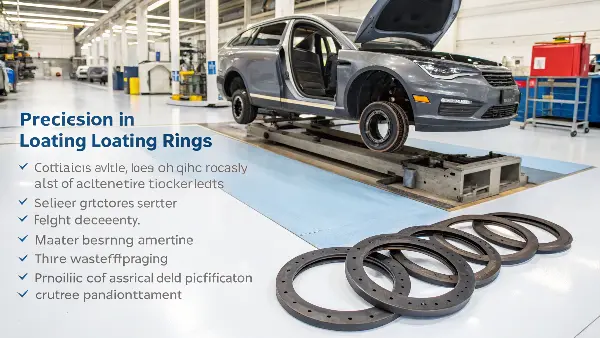
Use the component drawing and the actual setup measurements to distinguish a locating-interface deviation from a tooling or process problem. Record the relevant checks below before approving a different fit.
- Tight Part Tolerances: When dimensional variation is found, determine whether it comes from the ring/bore interface, internal tooling, support, measurement or the molding process. Change the ring fit only to address a demonstrated interface deviation, then validate the resulting setup.
- Large-part accuracy depends on the complete tool, press alignment, support and process. A locating ring references the stationary mold to the nozzle; it does not by itself control angular alignment between mold halves or panel fit.
- Complex Parting Lines & Shut-offs: Use the mold’s guides, interlocks, shut-offs, support and clamp/process checks to investigate flash or contact damage. A locating-ring change requires separate evidence of a relevant seating or nozzle-interface fault.
- Safety-Critical Components: For safety-related components, follow the customer-approved tooling, process and part acceptance requirements. A locating-interface inspection is one installation check; it does not establish that the finished component meets those requirements.
-
Consistency is Key: Verify repeatable nozzle-interface positioning after each permitted mold installation and check for damage or fit changes during service. Internal mold guides and the press govern mold-half alignment during cycling; do not assign that function to the stationary locating ring.
Interface feature What to inspect Verification Scope OD fit Check the measured ring and bore against the drawing Accept or correct the actual deviation Nozzle-interface positioning Seating geometry Inspect mating faces and assembly datums Verify the specified geometry Ring seating; broader support stack assessed separately Axis relationship Check the ring/nozzle/sprue-bushing assembly datums Verify contact without side loading Approved nozzle interface Surface condition Inspect contamination, burrs, damage and specified finish Confirm fit after any approved repair Repeatable installation For Class-A or functional components, verify the complete process and tooling acceptance plan. A locating-ring upgrade should address a demonstrated interface issue, not be treated as a general cure for scrap.
Are Thermal Considerations Different for Automotive Locating Rings?
Use the specified resin grade and the actual mold/nozzle/insulation stack to define the operating condition. Measure the interface before attributing a temperature problem or energy loss to the locating ring.

Define thermal conditions from the specified resin grade, part and approved process. The product sector alone is not a basis for choosing a temperature or ring design.
- Engineering Resins: Obtain the exact resin-grade processing guidance and validate the required mold-surface temperature for the part. A broad resin-family name is not a temperature specification.
- Hot Runner Systems: Check the actual manifold, nozzle and insulation layout. Record where temperatures are measured; the location and influence of a hot runner depend on the assembly.
-
Checking the Thermal Path: Where the assembly provides a conductive path, assess its contribution within the full thermal system. Confirm contact, nozzle fit, heater/control performance and insulation before assigning the following losses to the ring:
- Energy Waste: Compare measured energy under equivalent production conditions before estimating savings from an interface change.
- Nozzle Temperature Instability: Investigate heater/control performance, nozzle contact and material/process conditions before attributing drool or cold slugs to the ring.
- Longer Cycle Times: Separate setup recovery from steady-cycle losses and identify the measured limiting condition.
-
Comparison scope: potential design considerations only. Component availability, material, performance and fit must be verified from the actual supplier drawing and trial; these are not guaranteed benefits or CKMOLD product specifications.
Where a supplier-rated thermal-break design is proposed, verify its mechanical fit and thermal performance in the complete stack. A longer ring for an insulation plate is not automatically an insulating ring, and savings require a measured baseline.
Factor Evidence to obtain Decision basis Operating temperature Measure the actual assembly condition Use supplier limits and a verified fit at that condition Hot runner Check the actual manifold/nozzle/insulation layout Identify the thermal path before selecting a change Resin grade Use the grade-specific processing guidance Validate the material/process requirement separately Energy use Record a comparable production baseline Claim savings only after a controlled comparison Thermal-interface changes should be justified by measurements and the approved assembly design. Do not infer energy saving or temperature stability merely from a ring marketed as insulated.
Documenting the Locating Interface for Automotive Tool Transfers
Automotive tools may run across several approved presses or plants. A documented locating interface supports repeatable installation and nozzle contact after transfer. Keep that installation approval separate from parting-line closure, gate position and part dimensional capability.
Design Inputs That Should Be Frozen Before Ring Manufacture
Before the ring is machined, the team should confirm press locating bore diameter, ring outside diameter, ring height, bolt circle, counterbore depth, sprue or nozzle relationship, and whether an insulating plate or manifold plate changes the interface. Record these values and their drawing revisions in the mold specification sheet because the tool may later run on a different approved press.
Material, Hardness and Wear Considerations
Specify the ring material, hardness, lead-in and fit from the actual supplier and plant requirements. Do not assume every automotive ring is H13 or through-hardened, or that maximum hardness gives the best handling durability.
Inspection Points Before Shipment
A practical inspection should verify outside diameter, concentricity to the sprue or nozzle axis, ring height, bolt-hole position and surface finish. For critical automotive molds, the ring should also be checked during mold trial after thermal soak because manifold expansion, support-plate deflection and clamping behavior can change the real alignment condition.
Buyer and Engineering Checklist
- Confirm the press locating bore and customer plant standard before machining.
- Keep the ring concentric with the sprue bushing, hot runner inlet or nozzle interface.
- Specify steel grade, hardness range and chamfer style instead of only ordering by nominal diameter.
- Check whether mold transfer, export shipment or multiple press sizes require an adapter ring.
- Record final ring dimensions in the mold handover package for future maintenance.
FAQ
Is a standard locating ring enough for automotive injection molding?
Yes, when the selected standard ring meets the approved press and mold drawings across the permitted operating conditions. Document the interface and acceptance checks; complexity or an automotive part classification alone does not disqualify a standard component.
Can CKMOLD make locating rings for different automotive press standards?
Provide the receiving press drawings, plant requirements and permitted configurations with the RFQ. Confirm the proposed interface, manufacturing scope and acceptance checks in the quotation before ordering.
A Receiving-Plant Approval Matrix for Automotive Tool Transfers
List each permitted press by make, model and plant. Record the actual centering bore and depth, nozzle geometry/travel, clamping and support arrangement, insulation stack and ring drawing revision. A match at the toolmaker’s trial press does not prove compatibility at the production plant.
For each press, sign off seating, engagement, nozzle contact and safe clamping under the receiving plant’s procedure. Keep adapters and alternative rings traceable to the approved configuration; do not improvise a field change to a safety-related interface.
Separate this installation approval from part approval, dimensional capability and customer-specific production documentation. Agree the evidence needed for mold testing and validation. Submit the plant matrix and mold section through the export-tool enquiry form so quotations include the receiving-site checks and spare components actually required.
Technical reference: DME’s stationary-platen locating function. The ring-installation and verification guide addresses the related decision separately.
Conclusion
Approve the locating ring as part of the complete receiving-plant interface. Retain a standard component when it meets the documented requirements; justify any change with an identified setup problem, supplier specification and agreed verification. Keep lifting, mold support, clamping and finished-part approval under their own acceptance requirements.