
TPE overmolding succeeds when the exact TPE and rigid substrate are compatible, the interface is designed against peeling, and the process delivers a clean, hot flow front to that interface. Hardness alone does not predict adhesion, and a texture cannot make an incompatible material pair bond.
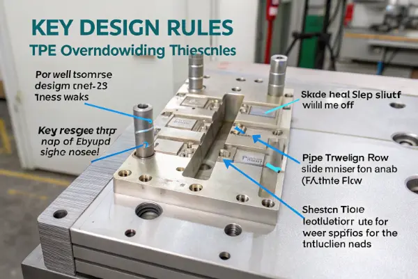
Choose between insert molding and two-shot molding
| Factor | Insert overmolding | Two-shot molding |
|---|---|---|
| Equipment and tooling | Conventional machine plus insert handling; separate substrate tool may be used | Multi-material machine, rotating/transfer tool and more complex integration |
| Interface temperature | Insert may cool before overmolding; preheating can be evaluated | Substrate is typically warmer when the second material is injected |
| Automation | Manual or robotic loading; placement error must be controlled | High integration and repeatability when the tool/process are stable |
| Program fit | Useful for prototypes, lower volume or pre-existing inserts | Can justify higher investment for stable, higher-volume production |
Volume alone should not decide the process. Consider quality risk, insert handling, cycle, mold size, part transfer, color changes and the cost of a second operation.
Material compatibility is grade-specific
Standard TPS or TPV compounds may bond to PP or PE, while overmolding onto PC, ABS, PC/ABS, PA, PBT, POM or other engineering resins often requires a grade formulated for that substrate. Teknor Apex’s overmolding selector demonstrates why a compatibility table names specific substrate families and TPE series.
Confirm the full substrate grade, including reinforcement, flame retardant, recycled content and mold-release package. Prototype the final color and material pair; do not assume a result from a generic resin name.
Design the interface before detailing the mold
- Keep overmold edges away from repeated fingernail or assembly peel loads.
- Avoid feather edges; use a controlled thickness and supported termination.
- Add holes, slots, undercuts or wrap-around features when mechanical retention is acceptable.
- Use radii and gradual transitions to reduce tear and stress concentration.
- Provide steel shutoffs that control flash without damaging the substrate.
- Place gates to avoid long, cooling flow paths across the bond surface.
- Vent the end of fill and enclosed interface pockets.
Control the process variables that affect adhesion
The material supplier’s data sheets define the starting window. Within that window, adhesion can be influenced by substrate cleanliness and temperature, TPE melt temperature, injection speed, interface pressure and time before the second shot. Moisture or release agents can interfere with the interface.
Run a structured study rather than changing several settings at once. Record actual melt temperature, insert temperature, fill time, transfer time and cavity pressure where available. Excess heat or residence time can degrade the TPE or damage the substrate, so “hotter is always better” is not a valid rule.
Diagnose common failures in the right order
| Symptom | First checks | Potential correction |
|---|---|---|
| Clean separation at interface | Exact material pair, contamination, insert temperature, flow-front temperature | Correct grade, remove release, improve heat/flow, add retention |
| TPE tears but remains bonded | Section thickness, notch, tear strength and demolding load | Radius/section change, higher-tear grade, gentler ejection |
| Flash at boundary | Shutoff fit, insert position, clamp force and pressure | Repair steel/fixture, stabilize insert, tune pressure after fill is stable |
| Short shot or flow marks | Gate size/location, venting, melt temperature and speed | Improve flow path/vent, then optimize grade-specific process |
| Variable bond by cavity | Fill balance, insert temperature, venting and material handling | Balance cavities and monitor cavity-specific conditions |
Define acceptance beyond appearance
Use a peel, pull-off, leak, torque or functional test that matches the part load. Record sample conditioning, direction, speed and failure mode. Repeat after heat, humidity, cleaners, UV or sterilization relevant to the product. A hand peel immediately after molding is useful for screening but not a complete production specification.
Send the CAD model, rigid and TPE grades, target hardness, cosmetic zones, annual volume, environmental exposures and bond acceptance method for DFM analysis. CKMOLD’s insert molding and overmolding service can assess interface, gate and tool risks. Use request a quote for project feedback.