
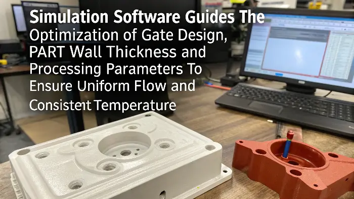
Flow simulation can help identify jetting risk before a mold is built, especially when the gate enters an open cavity, a thin wall or a visible surface. It does not replace a short-shot study or trial, but it can compare gate concepts and show whether the predicted flow front is supported by the surrounding geometry. The result is most useful when it leads to a specific design or process decision.
Related CKMOLD resources: DFM analysis, mold design, rapid tooling.
What is Moldflow simulation, and how does it actually work?
Confused by the term “Moldflow simulation”? It might sound complex. But it’s a key tool I use for achieving better injection molding outcomes by predicting how plastic flows.
Moldflow simulation, often called Mold Filling Analysis (MFA), uses specialized software to digitally replicate the entire injection molding process. It clearly shows how melted plastic will fill a mold, helping engineers like us identify and fix potential issues before they become real problems.
How can you specifically avoid jetting in injection molding using this software?
| Is that frustrating jetting defect creating ugly, snake-like marks on your parts? This is a common headache. Simulation software pinpoints why jetting happens and, more importantly, helps you stop it effectively. To avoid jetting using flow simulation, you carefully analyze the predicted flow pattern from the software. Then, you can virtually adjust design elements like gate design and location, or process parameters like injection speed, until the simulation shows the jetting pattern has disappeared. 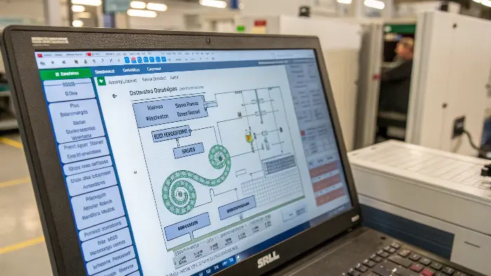 Jetting is a persistent problem I’ve helped many clients, much like your company the project stakeholder, overcome. It shows up as that characteristic worm-like or meandering stream of plastic on the surface of a molded part. This defect occurs when the molten plastic shoots too quickly into an open area of the mold cavity without making proper, gradual contact with the mold walls. Flow simulation software is absolutely brilliant for tackling this specific issue. It visually demonstrates where and why jetting is likely to occur under a given set of conditions. Once we see the potential for jetting in the simulation results, we can start making virtual changes. For instance, we might experiment with the gate location. Moving the gate so that the plastic impinges on a core pin or a mold wall can often solve the problem. Sometimes, simply changing the type of gate or its dimensions makes a significant difference. We can also play around with the injection speed profile directly in the software. A common strategy I’ve used successfully is to program a slower initial fill speed to establish a stable flow front, followed by a faster speed to complete the fill. The beauty of the software is that it lets us test all these ideas virtually, iteration after iteration, without wasting machine time or material on costly trial-and-error. Here’s a simple table showing how simulation guides adjustments: |
Parameter | Problematic Setting (May Cause Jetting) | Optimized Setting (Helps Prevent Jetting) | How Simulation Helps Identify & Test |
|---|---|---|---|---|
| Gate Location | Direct flow into open cavity region | Flow impinges on a wall or core pin | Visualize flow path, test new locations | |
| Gate Size | Too small (leading to high velocity) | Optimized for controlled flow rate | Predict melt velocity, test different sizes | |
| Injection Speed | Consistently too fast, uncontrolled | Profiled (e.g., slow initial, then fast) | Simulate effect of various speed profiles | |
| Melt Temperature | Too high (making plastic too fluid) | Optimal range for the specific material | Analyze material viscosity and flow front |
By using these insights from the simulation, we can proactively design out the jetting problem.
How do you prevent those annoying flow lines in injection molding projects?
Are you seeing visible flow lines on the surface of your molded parts? These surface defects can be tricky to eliminate. Simulation can be your guide to achieving smoother, consistent finishes.
You can prevent flow lines by ensuring the molten plastic flows uniformly and maintains a consistent temperature as it fills the mold. Simulation software helps optimize gate design, part wall thickness, and processing parameters to achieve this smooth, consistent flow.
Flow lines are another type of surface blemish that can really frustrate product designers and quality teams. They often look like ripples, waves, or lines of different gloss on the part surface. These usually appear near the gate or where different fronts of molten plastic meet and cool at slightly different rates. While they are distinct from jetting, flow lines are also fundamentally related to how the plastic material flows and solidifies within the mold. I’ve found that flow simulation software is very helpful in tackling this issue as well. It allows us to see exactly how the plastic fills every intricate detail of the mold cavity.
Several factors contribute to flow lines, and simulation helps us analyze them. One key factor is maintaining a consistent wall thickness in your part design. Sudden or drastic changes in wall thickness can cause variations in flow speed and cooling, leading to flow lines. Gate placement is also critical; we want the plastic to flow smoothly and evenly throughout the part. Processing parameters like injection speed, melt temperature, and mold temperature play a very significant role. The software allows us to virtually fine-tune these settings. By simulating different scenarios, we can find the optimal combination that minimizes temperature variations and abrupt velocity changes in the melt front. This detailed analysis helps us achieve parts without those distracting flow lines, ensuring a better aesthetic outcome.
Considering all the options, what is the best flow simulation software for injection molding tasks?
Model the Actual Gate and First Flow Region
Jetting often begins in the first few millimeters after the gate, so the model needs a realistic gate, runner transition, thickness and nearby wall or obstruction. A simplified gate can hide the very behavior the team is trying to predict.
Compare Gate and Speed Alternatives
Simulations can compare an edge, fan, tab, submarine or other gate concept, as well as initial speed profiles and melt temperature assumptions. The goal is not the most attractive plot; it is a flow pattern that enters the cavity in a controlled way without creating a new weld-line, air-trap or cosmetic problem.
Use Material Data With Appropriate Confidence
Viscosity, thermal properties, processing window and filler information affect the predicted flow. A generic material card can be useful for early screening, but final decisions should use the exact grade where possible and clearly identify data limitations.
Translate Results Into Tooling Actions
If the analysis predicts free jetting, consider gate reorientation, a supporting wall, a flow tab, a changed gate size or a staged speed profile. Document the reason for the action and the expected trade-off. A simulation report should help the moldmaker build a better tool, not simply archive a screenshot.
Correlate With the Real Trial
After tooling, run short shots and inspect the gate region, flow mark, weld lines and air traps. If the observed flow differs from the prediction, review the gate, material, temperature, mesh and boundary conditions. Correlation improves the value of later analyses.
Flow Simulation Predict Jetting Before Mold Steel Is Cut: Buyer Review Checklist
- Model a realistic gate, runner transition, wall thickness and first flow region.
- Compare gate location, gate style, speed profile and melt-temperature alternatives.
- Use the exact resin grade or state the confidence and limitations of the material data.
- Convert predicted jetting into a gate, geometry, venting or process action with a trade-off.
- Verify the prediction with short shots and trial observations after tooling.
FAQ
Can simulation prove that jetting will occur?
It can indicate a high-risk unsupported flow pattern, but real material, machine and mold conditions still need to be verified in trials.
Is simulation necessary for every mold?
No. It is most useful when gate placement, thin walls, appearance, complex flow or correction cost makes early analysis valuable.
Conclusion
In short, flow simulation software empowers you. It helps predict and prevent jetting and other defects, optimizing designs and processes for better quality molded parts.