
Tired of fighting molding defects like burn marks, short shots, and bubbles? These can total production runs, waste expensive materials, and delay projects. The real culprit may not be with your process or your material at all but with a critical, often-ignored detail: the venting system in your mold. Knowing how this system works is how to solve these chronic problems once and for all.
Mastering injection mold venting means designing a deliberate gas-release network from the first flow review through production maintenance. Vent location should follow the predicted flow front and actual air-trap risk; dimensions should support gas escape without flash; and the vent must remain clean and accessible after repeated cycles. A vent drawing should be reviewed with gates, cooling, ejection and parting lines, not as an isolated detail.
Related CKMOLD resources: mold design, DFM analysis, mold testing and validation.
Mastering the design of the venting system means focusing on three areas: dimensions, locations, and configurations. You need to calculate the vent depth for your particular plastic material in order to allow the air to escape without allowing plastic to leak out. Next, you’ll place vents at the final fill points and anywhere air could get trapped. Finally, you select the right type of vent-parting line or pin vent-that works with the geometry of your part. Getting these elements right is fundamental to producing quality, defect-free parts consistently.

Let’s begin with the foundational an ideas.
What Are the Fundamental Principles of Mold in Venting System Design?
Such a question I have generally asked is why certain molds are reliably run and certain are a continual fight? You go by all the routine and still, there are defects appearing. When you could not tell the cause of the issue, it is so frustrating. The solution is often found in the fundamental principles of the process of how air must be removed out of the mold cavity during injection. It is the beginning of consistent success to understand this.
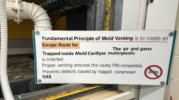
The basic concept of the mold venting is to make a hole through which the air and gases inside the mold cavity can escape when molten plastic is being injected. This passage should have some size that would enable the gas to move away fast but at the same time small so that the plastic would not leak away. Venting properly makes sure that the cavity fills out all the way, defects due to trapped and compressed gas are avoided, and the final part is of a high quality and structural integrity.
When molten plastic rushes into a mold cavity at high speed and pressure, it displaces the air that’s already inside. If that air has nowhere to go, it gets compressed into a tiny pocket. This compression rapidly heats the air to extreme temperatures, often high enough to scorch the plastic. This is what causes those ugly brown or black “burn marks” on your parts. This phenomenon, known as the diesel effect, is a direct result of poor venting. It’s not just about the air originally in the cavity; some plastics also release volatile gases when heated, and these also need to escape.
Why Trapped Air is So Destructive
Gas that is trapped does not merely burn the plastic. It also develops back pressure which opposes the incoming flow of material. This may help the mold to fill up before it is full and hence a short shot where the part may be left incomplete. The air trapped may also pose pores or bubbles in the part forming weak points undermining the structural integrity. When I was young, I was doing a project on an electronics enclosure which could not pass drop tests. The cause? Poor venting created microscopic bubbles that could not be seen by naked eyes.
The Balancing Act of Venting in Venting System Design
The goal is to provide an easy exit for the gas without creating an escape route for the plastic. This is the core challenge. The solution lies in creating shallow channels that are deep enough for low-viscosity gas to escape but too shallow for high-viscosity molten plastic to enter. Think of it like a screen door: it lets air through easily but keeps larger things, like insects, out. In our case, the “insects” are long polymer chains. The design must be precise to maintain this balance.
| Aspect | Poorly Vented Mold | Well-Vented Mold |
|---|---|---|
| Gas Escape | Trapped, compressed, superheated | Easily escapes at low pressure |
| Cavity Filling | Incomplete fill (short shots) | Complete, uniform fill |
| Part Appearance | Burn marks, flash, sinks | Clean surface, crisp details |
| Structural Integrity | Porosity, weak weld lines | Solid, strong part |
| Cycle Time | Slower cycles to avoid defects | Optimized, faster cycle times |
Ultimately, a good venting system allows you to run your process at its optimal speed and pressure, leading to better parts, shorter cycle times, and lower costs.
What Venting Mechanisms Are Available?
Common paths include parting-line vents, vented ejector pins or sleeves, vented inserts, porous plugs/inserts and vacuum-assisted systems. A valve gate controls melt flow; it is not itself a generic vent type. “Micro-venting” describes scale rather than one standardized mechanism.
| Mechanism | Useful location | Release check |
|---|---|---|
| Parting-line vent | Last fill or weld region reaching the split | Depth/land/relief, support and flash |
| Vented ejector/insert | Deep rib, pocket or below parting line | Witness, wear, cleaning and gas path to atmosphere |
| Porous vent | Localized inaccessible trap | Clogging, replacement access and surface witness |
| Vacuum assistance | Validated applications needing active evacuation | Seal integrity, timing, monitoring and fail-state |
How Are Vent Depth, Land, Width and Relief Released?
Vent dimensions are controlled tool features, not universal resin-family numbers. Start with the exact material supplier/toolmaker guidance, location and acceptable flash; then confirm with short shots, cavity/process evidence and measured trial results. The primary land meters the polymer, while wider/deeper secondary relief carries gas to atmosphere without an unintended restriction.
Record each vent ID, depth, width, land, relief route, measurement method and maintenance limit. Rework only the affected location and retain before/after dimensions.

Best Practices for Injection Mold Venting Design
Optimal Injection Mold Venting Design.
Venting plays a very important role in the design of injection molds in order to produce quality products. Best practices must be adhered to in order to have effective venting of molds. The right size and location of the vent should be in accordance with certain plastic materials.
Ventilation is planned to avoid such problems as traps of gases and burns. The appropriate selection of the vent locations also reduces the defects that are visible on the final product surface. Venting designs should be in line with flow properties of various plastics.
The cooperation of a designer of molds and material experts improves the effectiveness of venting. The collaboration enables the provision of viable solutions that suit special project requirements. Venting considerations included at the design stage will save on expensive redesigns at a later stage.
Optimize venting design using a checklist:
- Measure plastic flow characteristics.
- Identify optimal location and vent size.
- Focus on strategic vent locations.
- Co-operate with material specialists.
- Include venting requirements at the design stage.
The implementation of these best practices results in a better performance of mould. They assist in checking the quality of parts and their timely production. The design of venting is planned thoroughly, which improves efficiency and product results.
Where Are the Best Locations to Place Vents in a Mold?
You have made your vents of the appropriate size, however, when you install them on the inappropriate location, they become absolutely useless. Air will not be trapped and you will be left with your head bent in bewilderment as to why you still have parts that are malfunctioning. It is a widespread and irritating issue. The trick lies in anticipating the direction the air is going to and providing it with a way out at the point.
Vents are to be mostly located at the end of material fill in the mold cavity. It is here that the air is pushed and trapped automatically as the plastic moves on. It should also be provided with vents to any local high points, ribs or deep pockets where the air can be trapped. These final fill locations and air traps can only be predicted using the mold flow simulation software as the most accurate method of ensuring effective vent locations.
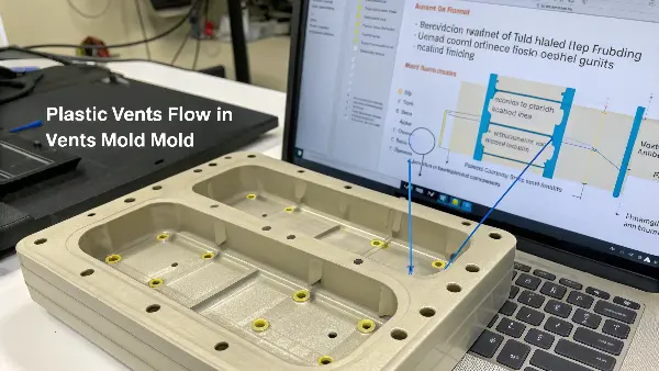
The number one rule for vent location is to place them where the part fills last. As the molten plastic flows from the gate and fills the cavity, it pushes the air ahead of it. This air gets cornered at the point furthest from the gate. If there’s no vent there, the air has nowhere to go. Back in the day, we relied on experience and a bit of guesswork to find these spots. We would do a “short shot” test, injecting just enough plastic to partially fill the cavity, to see the flow pattern and predict the last fill point.
Using Technology for Precision
A much better tool is available today, mold flow simulation. This computer program enables us to computerize the process of injection before any piece of steel is cut. It not only tells us the way the plastic will flow, in which places we will have the weld lines, but, probably and most importantly, where the last fill points and possible air traps will be. I would not leave out a flow analysis of a new or complex part. The low initial investment would save tens of thousands in rework of molds and production time loss. It removes all the guesswork.
Key Locations for Venting
Besides the last point of fill, there are other common areas that often need venting.
- Weld Lines: When two plastic flow fronts meet, they trap a line of air between them. This creates a weak spot known as a weld line or knit line. Placing a vent directly on this line allows the trapped air to escape, resulting in a much stronger bond.
- Deep Ribs and Bosses: Air can easily get trapped at the top of tall, thin features like ribs or screw bosses. The plastic flows up both sides and traps a pocket of air at the very end. Venting these specific features is often necessary.
- Parting Line: The easiest place to add a vent is on the parting line of the mold—the surface where the two halves meet. For most parts, it’s recommended to have vents around at least 30% of the parting line perimeter.
What Are the Different Vent Configurations and When Should You Use Them?
You understand where to locate vents and what they are supposed to be, but what are they supposed to look like? It is not necessarily possible or effective just to cut a simple channel on the parting line, particularly when the part geometry is complicated. The inappropriate type of vent can be as bad as having no vent at all resulting in constant defects.
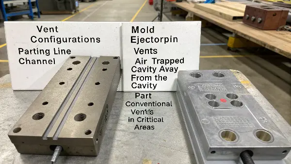
A parting line vent is the most popular type of vent; it is used in simple parts, where the air is confined in the split line of the mold. Where air is present in the cavity, and remote to the parting line, ejector pin vents or special vent pins are to be used. Porous mold inserts are an upscale product that is used in areas with a high level of care where traditional vents cannot be used so the gas is released in the steel itself.
Standard Venting Configurations
Advanced and Specialized Venting Solutions
Sometimes, conventional methods just aren’t enough, especially with high-gloss finishes or gas-sensitive materials.
| Vent Type | Best Use Case | Advantages | Disadvantages |
|---|---|---|---|
| Parting Line Vent | Perimeter of the part | Simple, low-cost, easy to maintain | Only works on the parting line |
| Ejector Pin Vent | Internal features, bosses, cores | Utilizes existing components, cost-effective | Limited to ejector pin locations |
| Dedicated Vent Pin | Specific, isolated internal air traps | Precise, targeted venting | Adds complexity and cost to the mold |
| Porous Inserts | High-aesthetic surfaces, deep ribs | Excellent venting, eliminates burn marks | High cost, can clog over time |
Approve Venting With a Trial Evidence Pack
Require the predicted/observed last-fill map, short-shot series, vent drawing, exact resin/process condition, flash and burn acceptance, and maintenance access. A successful sample at one setting is not enough if the approved production window can close the vent with flash or recreate trapped gas.
Primary technical sources checked: DME — Venting Solutions (mold-vent design and maintenance options). Apply the cited scope to the exact grade, tool and acceptance plan.
Place Vents at the Gas Destination
The last-to-fill location, weld-line region, rib end, insert boundary, deep pocket and parting-line dead end are common candidates. Flow direction can change with gate, speed, temperature and cavity balance, so use a realistic fill review and keep room for trial correction.
Define Vent Land and Depth
A vent usually has a short land at the cavity followed by a deeper escape path. The cavity-side feature must be shallow enough to avoid flash for the resin and pressure, while the path beyond the land should allow gas to travel away. Tool steel, resin, texture, surface and maintenance affect the practical dimensions.
Use Ejector, Insert and Porous Venting
Ejector pins, slides, inserts, porous materials and dedicated vacuum or overflow features can vent areas that a parting line cannot reach. Each option introduces sealing, wear, cleaning, alignment or replacement requirements that should be included in the mold specification.
Balance Venting With Flash Control
A vent can be technically open but functionally poor if it is blocked, misaligned or too far from the gas trap. A vent can also flash if the parting line opens or the land is damaged. Review clamp, local pressure, shutoff, vent land and inspection together.
Design for Cleaning and Verification
Provide access, vent maps, cleaning tools, inspection gauges or depth checks where appropriate. Record vent condition during preventive maintenance and use defect trends to decide whether a vent needs cleaning, polishing, re-cutting or a design change.
Injection Mold Venting Design: Buyer Review Checklist
- Map vents to last fill, weld lines, ribs, inserts, pockets and predicted air traps.
- Specify cavity land, escape path, steel, resin, pressure and flash assumptions.
- Evaluate ejector, insert, porous, overflow or vacuum venting where parting vents cannot work.
- Check shutoff, clamp, local pressure, vent damage and cavity flash risk.
- Provide vent access, cleaning instructions, inspection and maintenance records.
FAQ
Where should an injection mold vent be placed?
Place it where air is predicted or observed to finish, including last-to-fill regions, weld lines, rib ends, inserts and deep pockets.
How can venting be improved without creating flash?
Use controlled vent land and depth, clean the path, protect shutoffs and validate local pressure and flash behavior with trials.
Conclusion
Learning how to vent molds has nothing to do with a secret formula, but rather it should be systematically applied through proven principles. With a little thought of the correct dimensions of the material you are going to use, where exactly the air is trapped, and the best arrangement of the vents to use in your part geometry you can help remove an enormous selection of the most common molding defects. This information will make venting your operations a source of problems and a potent tool to accomplish quality, efficiency, and profitability.