
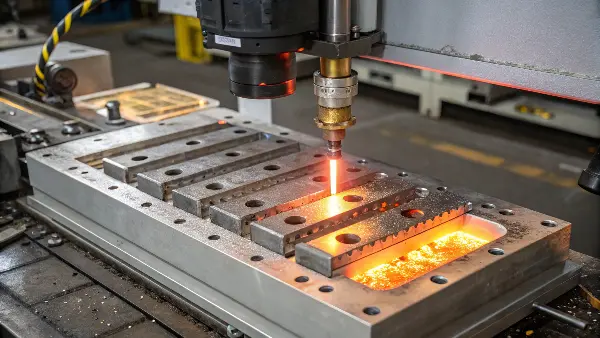
Quick answer: Validate mold temperature as a measured thermal system, not as one controller setpoint. Confirm circuit identity and flow, measure representative steel surfaces after thermal stabilization, link temperatures to critical part results, challenge the practical window and release reaction rules for utilities, startup and maintenance.
Use Why Mold Temperature Matters for Different Plastic Materials for the material-dependent role of mold temperature. This article isolates temperature validation for critical part characteristics.
Release Decision Matrix
| Validation layer | What to record | Acceptance logic |
|---|---|---|
| Utility | Supply/return temperature, flow, pressure and connections | Each circuit delivers repeatable heat-transfer conditions |
| Mold | Surface or embedded temperatures at named locations | Hot/cold pattern remains within approved limits |
| Part | Dimensions, surface, weight, warpage and function by cavity | CTQs remain acceptable across the thermal window |
| Time | Startup cycles, pauses, restart and long-run drift | Defined stable state and recovery procedure |
Approval Checklist
- Identify temperature-sensitive product CTQs and measurement condition.
- Map, label and verify every cooling, heating and hot-runner circuit.
- Record supply/return temperature, flow, pressure and equipment identity.
- Measure representative mold-surface locations with a repeatable method.
- Define startup stabilization, pause and restart behavior.
- Challenge low, center and high thermal conditions by cavity.
- Set production monitoring, alarm, containment and reaction rules.
- Link circuit maintenance and mold transfers to revalidation triggers.
Define the Thermal CTQs
Identify part results expected to respond to mold temperature: gloss, weld-line strength, replication, crystallinity, shrinkage, flatness, dimensions, residual stress and ejection stiffness. State measurement timing and conditioning. This determines where temperature evidence is needed and how wide a window must be challenged.
Use the exact resin and grade guidance as boundaries. Amorphous and semicrystalline materials respond differently, and fillers or wall distribution can make one region more sensitive than the average.
Map Every Circuit and Heat Source
Create a circuit diagram with inlet, outlet, baffles, bubblers, series paths, manifolds, inserts, slides, hot-runner zones and expected flow direction. Label hoses and verify connections on the machine. A setpoint cannot reveal a blocked passage or reversed circuit.
Measure flow and pressure where practical and inspect water quality, scale and leakage. Record controller, chiller, pump and hose capability. The released setup should be reproducible without relying on operator memory.
Measure the Mold, Not Only the Controller
Controller supply temperature differs from cavity-surface temperature because heat enters from the melt and leaves through steel and coolant. Select repeatable surface locations near critical features and known hot or cold zones. Use calibrated contact or infrared methods with documented timing and emissivity limitations.
For high-consequence or inaccessible regions, embedded sensing may be justified. The goal is representative evidence, not a large number of measurements that cannot be repeated in production.
Establish Thermal Stabilization and Recovery
Track surface temperature, part result and cycle number from startup until a defined stable state. Include the effect of planned pauses, mold opening time and material interruptions. Specify which samples can be accepted during warm-up and how restart is confirmed.
A stable controller display does not prove the steel and parts are stable. Thick cores and actions may require more cycles. Use trend evidence to set a practical startup rule and avoid mixing transient parts into capability studies.
Challenge the Thermal Process Window
Run planned low, center and high conditions within material, mold and equipment limits while holding other factors controlled. Measure CTQs by cavity and note interactions with cooling time, fill, packing and ejection. A window should show acceptable product and reasonable operating margin, not only a single best recipe.
Avoid changing coolant temperature and cooling time together without a plan. Use a designed experiment when interactions are important. Document limits that protect both quality and safe equipment operation.
Release Monitoring and Reaction Rules
Define what production records: controller setpoint, circuit flow, supply/return temperature, named surface check or a correlated part signal. Set alarm and reaction logic for loss of flow, temperature drift, wrong connections and restart. Include inspection and containment responsibilities.
Connect preventive maintenance to the mechanism. Scale, corrosion, leaking seals and hot-runner heater failures alter the thermal state. Review process capability after circuit repair, mold transfer or resin changes that can shift heat load.
Illustrative Thermal Validation
Illustrative engineering example—not a claimed CKMOLD customer result: A four-cavity cosmetic cover meets dimensions at startup but develops gloss mismatch after 40 cycles. Circuit mapping finds two cavities share a restricted series loop. The team records flow and surface temperatures, changes the circuit arrangement and validates gloss and flatness across low, center and high approved conditions before releasing a flow check.
Supporting Review Resources
Questions Before Approval
Is controller setpoint the same as mold temperature?
No. Surface temperature depends on melt heat, steel, circuit design, coolant flow and time as well as the supply setpoint.
How many cycles are needed before sampling?
The number is tool- and process-specific. Use temperature and part trends to define a stable state rather than a generic count.
Why measure coolant flow?
Heat transfer can change when a passage blocks, a hose is wrong or a pump cannot deliver the required flow even though temperature display looks normal.
When should mold temperature be revalidated?
Review after circuit repair, mold transfer, utility changes, resin changes or other events that can alter the thermal system and CTQs.
Apply the Mold-Temperature Validation Plan for Critical Part Quality review to your released design. Share the function, exact resin, annual volume, CTQs, cosmetic limits and launch timing through the CKMOLD project form. If CAD is relevant, send it directly to jerry@ckmold.com; the form does not require an upload.