
Ejector-pin marks are not solved reliably by changing one machine setting. The mark is evidence that the local ejection force, part rigidity, residual stress and support area are out of balance. A useful investigation maps the defect, separates process effects from tooling constraints, then validates any correction across cavities and a controlled process window.
Disclosure: The workflow below is an illustrative engineering method. It is not presented as a documented CKMOLD customer case, and the dimensions and results are not claimed project data.
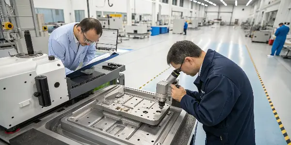
First classify the visible mark
Record cavity, ejector number, distance from ribs or bosses, gate relationship and whether the defect appears as a depression, raised witness, gloss change, whitening, crack or local deformation. Photograph the same lighting angle and measure depth or height when the acceptance criterion requires it.
| Symptom | Likely mechanism to investigate | Evidence to collect |
|---|---|---|
| Circular depression | High local force while the part is soft or poorly supported | Part temperature, cooling time, pin area and local wall section |
| White stress halo | Tensile strain, sticking, sharp contact or brittle/condition-sensitive resin | Draft, polish direction, moisture/conditioning and slow ejection trial |
| Raised ring or flash | Clearance, pin fit, wear or cavity pressure | Pin/bore inspection, pack-pressure study and cavity-specific comparison |
| Crack or puncture | Excess force on thin/unsupported geometry | Section thickness, pin edge, support and ejection sequence |
| Mark only in one cavity | Local tooling, cooling or balance issue | Cavity map, temperature/flow comparison and component inspection |
Do not call every circular feature an ejector defect. Some witness is inherent to the mechanism, and the drawing should define which surfaces are cosmetic and what mark is acceptable.
Confirm that the part can release
Check pull direction, draft, texture, core polish direction, undercuts, vacuum effects and shrinkage around cores. Measure actual draft and look for scuffing that identifies the sticking surface. A process change may reduce the symptom without removing the mechanical lock.
Deep ribs and bosses can grip the core even when the outer wall has draft. Textured surfaces and high-shrinkage materials often need additional release allowance. Mold-release spray can hide the mechanism and introduce contamination or paint/adhesion issues, so it should not be the default diagnosis.
Determine whether the part is rigid enough at ejection
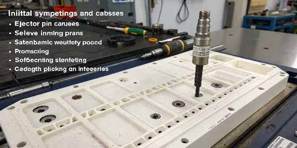
Cooling time, mold temperature, local wall mass and crystallization or glass-transition behavior influence stiffness at mold opening. Measure or compare part temperature near the defect rather than relying only on the set cooling time.
Shorten and lengthen cooling in controlled steps while holding other variables stable. If the mark improves strongly with additional cooling, the part may be ejecting too soft—but the long-term fix may still involve better cooling, more support or improved release rather than accepting an uneconomic cycle.
Separate packing stress from ejection force
Excessive pack pressure or hold time can increase contact pressure against the core and make release more difficult. Too little packing can create sink or dimensional loss. Use a gate-seal or part-weight study to understand when additional hold stops adding useful mass.
Review transfer position, peak pressure, cavity pressure if available, cushion repeatability and part weight by cavity. Change one controlled variable at a time. An apparent benefit from lower packing must be checked against dimensions, sink, strength and warp.
Inspect the ejector system as a load path
Ejection force should reach sufficiently stiff regions and be distributed so the part moves without bending. Review:
– pin diameter, edge condition and contact area;
– distance from ribs, bosses and unsupported cosmetic walls;
– balance around the part and expected center of resistance;
– pin length, plate parallelism, binding and return condition;
– ejector sleeves, blades, stripper plates or air assistance where appropriate;
– interference with cooling channels and moving components;
– allowable witness marks and access for maintenance.
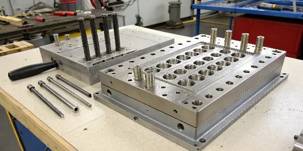
A larger pin lowers nominal contact pressure but may not fit the steel or cosmetic zone. More pins can improve support, yet poor balance can tilt the part. The solution is a complete load-path review, not a universal pin-count rule.
Use a staged diagnostic trial
An efficient trial sequence is:
1. map defects and establish a stable baseline by cavity;
2. inspect draft, undercuts, polish direction and visible scuffing;
3. challenge cooling time and mold-opening/ejection speed within safe limits;
4. review pack/hold using weight, dimensions and gate-seal evidence;
5. inspect pins, plate motion, balance and local support;
6. propose reversible process changes before steel work where appropriate;
7. validate tooling changes at nominal and boundary conditions.
Record material lot and condition, machine, mold circuit temperatures/flow, process settings, cavity identity, part conditioning and measurement method. Otherwise, two trials may not be comparable.
Illustrative engineering scenario
Consider a large cosmetic ABS or PC/ABS trim panel with whitening around two pins near a deep rib intersection. Increasing cooling reduces the whitening but leaves a shallow depression and an unacceptable cycle. Short-shot and scuff evidence show that the part grips the core near the rib; the two pins carry a disproportionate load.
A rational team would compare draft and polish at that feature, check local cooling, review pack/hold, then evaluate added support or a different ejection element. The acceptance trial would confirm cosmetic limits, critical dimensions and part function across cavities and process-window challenges. The scenario explains the method; it does not assert a customer result or a percentage improvement.
When a tooling correction is justified
Tooling work becomes more likely when marks remain localized after a stable process is established, release geometry is inadequate, pin support is clearly unbalanced, cooling is asymmetric or a mechanical component binds. Document the proposed steel change, expected mechanism, dimensional risk, reversibility and validation plan before machining.
Use the mold testing and validation process to compare before/after evidence. For ejection layout changes, coordinate with injection mold design so added pins or cooling changes do not create new interference or maintenance risk.
Evidence to send for an ejector-mark review
Send close and wide part photos, cavity and ejector identification, material producer/grade, color/additives, wall and rib section, draft/texture, gate location, cooling layout if available, process sheet, part temperature or cooling comparison, part weight, defect trend and cosmetic/functional acceptance criteria.
Contact CKMOLD with the defect evidence. CAD and large files can be emailed directly to [jerry@ckmold.com](mailto:jerry@ckmold.com).
Technical references
– Protolabs: Design for Moldability Toolkit
– Covestro Part and Mold Design Guide
Diagnostic questions
Can more cooling remove an ejector mark?
It can increase part stiffness and reduce a mark, but the required cycle and underlying release/support problem still need review.
Should packing pressure be reduced first?
Only as a controlled trial. Verify dimensions, sink, part weight and function so a cosmetic improvement does not create another defect.
Are ejector-pin marks permitted on automotive parts?
That depends on drawing, cosmetic zone, mating function and customer specification. Define the acceptance limit rather than assuming no witness is allowed.
What proves that a mold change worked?
Comparable before/after evidence across cavities and agreed process-window conditions, with cosmetic, dimensional and functional acceptance confirmed.
The system-level sequence is explained in Ejector Pin Mark Root-Cause Analysis: Release Load, Timing and Support. This supporting guide concentrates on an automotive-part diagnostic method without customer claims.