
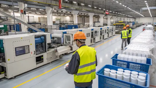
Quick answer: A changeover is difficult because a molding cell combines a heavy tool, material system, heat-transfer network, controls, moving actions, automation and quality release. Reliable changeovers reduce uncertainty through preparation, standardized connections, external work, safe verification and a defined path from first cycle to approved production.
Separate Internal and External Work
Internal work requires the stopped machine; external work can be done while the previous job runs. Pre-stage the mold, lifting equipment, clamps, adapters, resin, dryer, controller, robot tooling, gauges, documents and approved recipe. Confirm the next tool’s condition before the press is opened.
Measure changeover from last accepted part to first accepted part, while retaining safety and quality steps. Tracking only clamp-to-clamp time encourages hidden warm-up and approval delay.
Remove and Install the Mold Safely
Follow the site’s isolation, lifting and support procedures. Move actions to safe positions, disconnect energy and drain circuits as required. Inspect parting surfaces, locating, nozzle and ejector interfaces before installation.
Use standardized clamps, torque and support where possible. Confirm mold thickness, opening, robot clearance and ejector stroke. A fast installation that damages a locating ring or leaves inadequate support creates downtime later.
Process Control Map
| Changeover stage | Main risk | Control |
|---|---|---|
| Prepare | Missing mold, material, adapters, documents or labor | Pre-stage verified kit and schedule |
| Mechanical install | Misalignment, support, nozzle or ejector mismatch | Machine-mold checklist and torque standard |
| Connect and sequence | Wrong water, hot runner, action or robot setup | Labels, keyed interfaces and dry-cycle verification |
| First-off release | Transient or mixed-material parts accepted | Thermal stabilization, trace and quality gate |
Control Material and Purging
Verify old and new resin compatibility, temperature and purge procedure using material and equipment guidance. Clean loader, hopper, dryer and feed paths; label retained material. Heat-sensitive or incompatible polymers can degrade or react if purging is improvised.
Record lot, drying and color. Continue segregation until contamination and transition material are cleared. The first visually acceptable part may still contain a mixed material that changes strength or compliance.
Connect Thermal, Action and Hot-Runner Systems
Use circuit maps and labels for coolant supply and return, temperature-control units, valve-gate air, hydraulics, sensors, heaters and thermocouples. Verify flow and leaks before automatic cycling. Match hot-runner zones to the approved controller and inspect resistance or grounding according to procedure.
Dry-cycle slides, cores, ejector and unscrewing at safe speed. Confirm interlocks and home signals before the clamp can close.
Restore Automation and Mold Protection
Install end-of-arm tooling, confirm robot program and teach positions under controlled conditions. Check part and runner removal, cavity detection, conveyor or fixture orientation and reject path. Set mold protection from a verified low-force condition rather than copying an unrelated job.
Challenge one likely fault, such as missing part or action-not-home, to verify the cell reacts safely. Remove temporary overrides before production release.
Reach a Stable First-Off
Load the approved setup, then verify actual material and mold thermal state, fill time, pressure, cushion, weight, cycle and cavity balance. Define warm-up cycles and segregate transient parts. The setup sheet should distinguish fixed limits from normal starting targets.
Quality release should include required dimensions, appearance, function, cavity and traceability. Record deviations and setup time by cause. Improvement work should eliminate preparation and interface waste without weakening safety or evidence.
Authoritative References
Process Control Checklist
- Pre-stage mold, material, dryer, adapters, controllers, robot tooling and gauges.
- Verify safe isolation, lifting, locating, support, nozzle and ejector fit.
- Use approved material-change and purge procedures.
- Map and verify all coolant, heat, air, hydraulic and electrical connections.
- Dry-cycle actions, ejector, sensors and interlocks at controlled speed.
- Restore robot, removal, reject path and mold protection.
- Define thermal stabilization and segregate transient parts.
- Release first-off through documented process and quality evidence.
Illustrative Changeover Delay
Illustrative engineering example—not a claimed CKMOLD customer result: A mold is clamped quickly, but production waits because two water hoses are mislabeled, the robot gripper is stored elsewhere and the new nylon has not completed drying. The improvement standardizes circuit tags, pre-stages a verified changeover cart and adds a readiness gate before the previous job stops.
Implementation Questions
What is the best way to measure changeover time?
Measure from the last accepted part of the old job to the first accepted part of the new job and classify the causes of delay.
Why are startup parts segregated?
Material transition, temperature and process response may not yet represent the approved stable production state.
Can setup values be copied between machines?
They can be a reference, but machine geometry and controls differ. Verify physical process outputs and product results.
How can changeovers improve without reducing safety?
Move preparation outside stopped time, standardize interfaces, pre-stage verified kits and remove recurring causes while retaining required isolation and checks.
Implementation Resources
Apply the Injection Molding Machine Setup review to your released design. Share the function, exact resin, annual volume, CTQs, cosmetic limits and launch timing through the CKMOLD project form. If CAD is relevant, send it directly to jerry@ckmold.com; the form does not require an upload.