
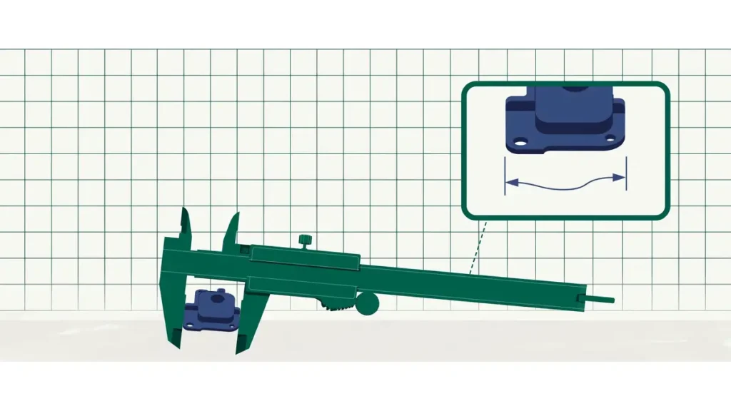
Your drawing says ±0.05 mm on every dimension. The quote comes back higher than expected, or the supplier asks which dimensions actually matter. Both reactions point to the same problem: the drawing asks the mold to do something no molded part can do on every feature at once.
The short answer: most molded dimensions follow a general tolerance band set by the resin and the part size — the ISO 20457 standard gives the framework — and only a few critical features justify tighter control. Every step tighter than that band adds tooling, process and inspection cost, so the cheapest accurate drawing is one that is tight where function demands it and general everywhere else.
Why Is a Molded Part Not a Machined Part?
A CNC-machined part starts as solid material and is cut to size. An injection-molded part starts as molten plastic, fills a steel cavity, cools, and shrinks. That difference is the whole story of molding tolerances.
Two tolerances are at work in every molded dimension, and they should not be confused:
- The tool tolerance is the accuracy built into the mold steel itself. Protolabs, for example, publishes a machining tolerance of ±0.003 in. (0.08 mm) for its injection molds. This is what the steel can hold.
- The resin tolerance is the variation of the finished molded part, driven mainly by how the plastic shrinks as it cools. Protolabs puts this at no less than ±0.002 in./in. (0.002 mm/mm) — and it grows with part size, resin choice and process variation.
A mold can be machined to ±0.08 mm and still produce parts that vary more than that, because the plastic itself moves after it leaves the steel. Shrinkage is not a defect to be eliminated. It is a material property to be predicted, compensated for in the steel, and then controlled with a stable process. When a buyer understands that, the conversation with a supplier changes from "hold this number" to "show me how this number is held."
What Is a Realistic General Tolerance for a Molded Part?
Most drawings do not need a tolerance on every dimension. They need one general tolerance that covers all the dimensions that are not individually toleranced, and tighter values only where function demands them.
The international standard for this is ISO 20457:2018, "Plastics moulded parts — Tolerances and acceptance conditions." It replaced the old DIN 16901 and internationalized the German DIN 16742 standard, and it groups molded parts into tolerance groups TG1 to TG8, from the tightest to the loosest. As a default for general injection molding work, the manufacturing platform Hubs applies the DIN ISO 20457:2020 TG5 class to any dimension that is not otherwise toleranced on the drawing. That is a useful reference point: if your drawing has no general tolerance block at all, your supplier is effectively guessing what you will accept.
Published standard values from the same Hubs guide show how loose the "standard" band really is once you look past the headline number:
| Feature | Published standard tolerance |
|---|---|
| Concentricity | ±0.125 mm |
| Roundness | ±0.175 mm |
| Flatness, dimensions up to 100 mm | ±0.400 mm |
| Flatness, dimensions above 100 mm | ±0.800 mm |
| Flash on any part | 0.125 mm maximum |
| Ejector marks | 0.125 mm maximum |
| Gate and runner removal (any method) | ±0.125 mm |
These are general tolerances for ordinary production — not the best a good tool can do, and not a promise for any specific part. They are the level at which a mold runs without special tooling, special process control, or special inspection. If your part needs better than this on a given feature, say so explicitly, and expect the quote to reflect it.
One practical rule follows from the resin tolerance above: tolerance should grow with size. A ±0.10 mm band on a 10 mm feature is a very different demand from ±0.10 mm on a 300 mm housing, because the resin tolerance alone contributes roughly ±0.002 mm for every millimetre of length. Long dimensions in high-shrink resins simply cannot carry the same absolute tolerance as short ones.
What Decides Whether Your Tolerance Is Achievable?
Five factors decide it, and only one of them is the mold.
1. The resin family
Shrinkage varies far more between resin families than between suppliers. Typical published shrinkage ranges — always confirm the exact grade on the resin manufacturer’s datasheet — look like this:
| Resin family | Typical mold shrinkage | What it means for tolerances |
|---|---|---|
| Amorphous, unfilled (ABS, PC, PMMA) | 0.4–0.8% | The most dimensionally stable group; the best starting point for tight features |
| Glass-filled (PA66-GF30, PBT-GF30, PPS-GF40) | 0.2–0.7%, but anisotropic | Low average shrinkage, but different along and across the flow direction — warpage risk |
| Semi-crystalline, unfilled (PA6, PBT, PEEK) | 0.8–1.8% | Larger and more variable shrinkage; moisture uptake in nylons adds further movement |
| High-shrink semi-crystalline (PP, HDPE) | 1.5–3.5% | The loosest general tolerances; tight features need careful justification |
| TPE / TPU (Shore 50A–90A) | 1.0–2.5% | Soft materials move after ejection and are hard to measure repeatably |
Changing resin to chase a tolerance is sometimes the cheapest fix available. Our material selection guide for precision injection molding works through that trade-off in detail.
2. Tool-bound vs. non-tool-bound dimensions
ISO 20457 makes a distinction buyers rarely see on drawings but always feel in the parts. A tool-bound dimension is formed inside one half of the mold — a pocket depth, a boss diameter. A non-tool-bound dimension crosses the parting line or is set by moving slides — a wall thickness, or any dimension spanning both mold halves. The second kind absorbs parting-line variation, guide clearance and slide deflection, and needs a wider tolerance. When a tight tolerance sits on a dimension that crosses the parting line, the mold has to work much harder to hold it.
3. Wall thickness and geometry
Uniform wall thickness is the quiet precondition of every tight tolerance. Thick sections cool slower, shrink more, and sink; thin sections freeze early and pack poorly. A part with a 1 mm wall next to a 5 mm boss will fight the tolerance on both features at once, whatever the mold costs. Ribs, bosses and gussets should be proportioned to the wall, not to the load alone — that is a DFM question, and our guide to reviewing a DFM report shows what to check before steel is cut.
4. Process stability
The same mold produces different parts when the process drifts. Scientific molding — controlling fill, pack and hold from cavity-pressure data rather than from operator habit — is what keeps a capable mold capable across a production run. A tight tolerance without a stable process is a sampling result, not a production result.
5. Measurement conditions
Plastic parts change size with temperature, humidity and age after molding. A dimension measured one hour after ejection is not the same dimension measured after 48 hours of conditioning, and a nylon part measured in a dry winter workshop is not the same part measured in a humid summer warehouse. State the measurement conditions on the drawing — temperature, conditioning time, and whether the part is measured as-molded or after aging — or the supplier and the buyer will argue about two different parts.
How Do Tight Tolerances Change the Price?
Tighter tolerances do not add one cost. They add cost in four places at once, and the quote has to carry all four:
| Cost driver | Standard tolerance | Tight tolerance on critical features |
|---|---|---|
| Tooling | Standard tool steel, conventional machining | Tighter steel tolerances, more fitting and try-out loops, sometimes higher-grade steel |
| Process | Standard process window | Narrower window, longer setup, more monitoring, slower cycle if cooling must be extended |
| Inspection | Sampling inspection, hand tools | More frequent checks, CMM or dedicated gauges, capability studies on critical features |
| Yield | Normal scrap allowance | Higher scrap and rework when the process window narrows |
Nobody can put a single percentage on that premium, because it depends on how many features are tight, how far they are from the general band, and how large the part is. But the direction is reliable, and the shape of the curve matters more than the number: the first step tighter than the general band is the cheapest, and each step after it costs more than the last. Tightening every dimension by the same amount is the most expensive way to buy accuracy you do not need. Tightening three features that decide whether the part assembles is usually cheap by comparison.
That is why quantity matters to the tolerance conversation. On a 500-part order, a capability study and a dedicated gauge can cost more per part than the parts themselves; on a 500,000-part order, the same work disappears into the unit price. If your quantities or repeat batches are still being planned, our guide to order quantity and repeat batches in the RFQ explains how batch planning changes what a quote can carry.
How Should You Write Tolerances on Your Drawing?
A drawing that gets comparable quotes has five habits:
- Name a general tolerance. Put an ISO 20457 tolerance group — TG5 is a common default — in the title block, so every untoleranced dimension has a defined band.
- Mark the critical features. Protolabs recommends calling out up to five Critical-to-Quality (CTQ) features in the CAD model, with their tolerances. Five is a discipline, not a limit: it forces the decision about what actually matters.
- Separate functional tolerance from production tolerance. The functional tolerance is what the assembly needs. The production tolerance is what the mold can hold. If they do not overlap, the design, the resin or the process has to change — a tighter number on the drawing will not fix it.
- Give the tight features a datum. A tolerance without a datum scheme is a wish. State which faces locate the part, and in which order.
- State the measurement conditions. Temperature, conditioning, and the age of the part at measurement, as above.
If you are unsure which features are critical, that is a useful question to send with the RFQ rather than a decision to make alone. A supplier who has molded similar parts can usually tell you within one review which three dimensions will decide the assembly — and which twenty will not.
Tolerance Checklist for Your RFQ
| # | Check | Why it matters |
|---|---|---|
| 1 | General tolerance block states an ISO 20457 group (e.g. TG5) | Every untoleranced dimension has a defined band |
| 2 | No more than five CTQ features, each with datum | The supplier prices the hard work, not a blanket |
| 3 | Tight features do not cross the parting line unless unavoidable | Non-tool-bound dimensions cost more to hold |
| 4 | Resin named by grade, not family alone | Shrinkage and anisotropy are grade-specific |
| 5 | Wall thickness is uniform or the variation is justified | Uneven walls fight every tolerance at once |
| 6 | Measurement conditions stated (temperature, conditioning, age) | Buyer and supplier measure the same part |
| 7 | Inspection scope agreed (sampling, CMM, capability study) | Inspection cost is visible before it is invoiced |
Frequently Asked Questions
Can I get ±0.02 mm on all dimensions of a molded part?
No — not as a production tolerance across a whole part. ±0.02 mm may be achievable on one small, tool-bound feature in a stable amorphous resin, with the right tool and a controlled process. Across every feature of a real part, in a real resin, it is not a molding tolerance. It is a machining tolerance applied to the wrong process.
Does a tighter tolerance always mean a better part?
No. It means a more expensive part, and sometimes a worse one: chasing an unnecessary tolerance can force a resin change, a thicker wall, or a process window so narrow that the defect rate rises. The best part is the one whose critical features are held and whose other features are left at the general band.
Who decides whether a tolerance is achievable?
The decision is shared. You define what the assembly needs. The molder shows what the resin, tool and process can hold, with sample data. If the two do not meet, the design, the material or the process changes — not the number on the drawing. Ask for that conversation at RFQ stage, when it is still cheap.
What to Send With Your RFQ
Send the 3D CAD file (STEP), a 2D drawing with the critical dimensions marked and a general tolerance block, the target resin grade, expected quantities, and the measurement conditions you will use at acceptance. Mark the features that decide assembly, and say which features are cosmetic. That package lets a molder quote the tolerance work once, accurately — instead of pricing the risk of a drawing that asks for everything.
Request a quote for your injection molded parts with your drawing and quantities, and we will review the tolerance plan with the DFM before quoting tooling.