
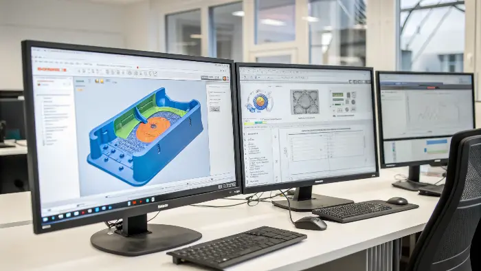
High injection pressure is a nightmare for delicate inserts. Low-Pressure Molding (LPM) with Moldflow analysis provides a soft yet efficient way to safeguard your precious parts.
Low-pressure molding is often used to encapsulate or protect delicate electrical and mechanical components without exposing them to the same mechanical stress as conventional high-pressure injection. Analysis can help evaluate flow path, fill time, pressure, temperature, air escape, insert movement and coverage. It is useful only when the model reflects the substrate, material and fixture conditions of the real assembly.
Related CKMOLD resources: insert molding and overmolding, mold testing and validation, mold design.
Low-Pressure Molding (LPM) uses Moldflow analysis to predict and maximize the injection of plastic melt into a mold at relatively low pressures. Material flow, heat, and pressure loss are modeled by the analysis. It helps engineers design effective molds and minimize defects, especially when handling fragile inserts, preserving component integrity and high-quality encapsulation.

It’s simple enough to recognize the benefits of low-pressure molding, but how does that translate to the application of simulation software? And what pressures are we even talking about, anyway?
Name the Pressure, Location and Process Phase
Pressure must be named by location and phase: hydraulic/drive pressure, machine-reported plastic pressure, nozzle pressure or modeled cavity pressure during filling/packing. They are not interchangeable, and one universal pressure range cannot represent all machines, materials, gates and geometries.
A useful analysis reports peak pressure, where and when it occurs, pressure at sensitive inserts/components, fill pattern, temperature history, air traps and the assumed transfer/packing conditions. Autodesk’s process-settings documentation separates filling, velocity/pressure switchover and packing; keep those assumptions visible in the report.

What “Low-Pressure Molding” Means Here
For electronics encapsulation, low-pressure molding commonly refers to a thermoplastic encapsulation process using application-specific polyamide or related compounds at lower process pressure than conventional high-pressure injection molding. It is not one standard pressure number and is different from structural-foam or reaction processes that may also use the phrase.
Henkel’s electronics-protection overview describes the process/application, while the TECHNOMELT PA 657 page shows that properties and processing belong to a specific grade. Use the selected supplier’s current technical and safety information.

The Relationship Between Mold Flow Analysis and DFM
DFM or Design for Manufacture is a manufacturing-led design approach that involves the manufacturability and cost-effectiveness of manufacture to be considered at the initial stages of product design. DFM encompasses the entire process of product development, from conceptual design to detailed design, process planning, and production manufacturing.
In the manufacturing of plastic parts (e.g., automotive, aerospace, medical, equipment, consumer goods, electronics, personal care, and most others), DFM usage in mold design is also necessary. By using DFM, designers can examine and enhance product designs to make them easier to manufacture. This includes examining manufacturability, determining the most appropriate manufacturing processes, and enhancing product designs to reduce manufacturing complexity and expense.
Summarily, mold flow analysis and DFM are both key methods in mold designing and production in the automotive manufacturing sector. They complement one another and can effectively improve the quality and productivity of production of the molds and reduce the production costs.
Use Analysis to Compare Pressure-Reducing Alternatives
Compare gate number/location/size, flow length, local section, fill sequence, venting and a feasible temperature/fill profile. Lower predicted pressure is useful only if coverage, sealing, adhesion, component temperature exposure, air management, dimensions and cycle remain acceptable.
Document exact grade data, component/cable geometry, insert restraint, contacts to remain exposed, gate/vent assumptions and machine controls. Treat the simulation as a comparison model and correlate it with pressure/temperature and functional results from a trial; do not present a modeled saving as a completed CKMOLD customer result.

Choose the Process From the Product Requirement
| Question | Why it matters |
|---|---|
| What must be protected, sealed or strain-relieved? | Defines coverage, interfaces and functional tests. |
| What temperatures, chemicals, electrical and mechanical loads apply? | Controls compound and process suitability. |
| Can components tolerate injection pressure and heat? | Controls restraint, support, gating and process choice. |
| What adhesion and rework are required? | May change pretreatment, material and assembly design. |
| What validation applies? | Defines samples, ageing, leak/electrical and destructive tests. |
Conventional injection molding may suit a structural housing; low-pressure encapsulation may suit sensitive assemblies when its material and qualification meet the environment. Some products need both. Review the actual assembly rather than selecting from pressure labels.
Select the Analysis Capability, Not a Generic Software Ranking
Confirm that the solver and material model represent the selected compound and process, and that the analyst can model the assembly, inserts, flow path, vents and thermal boundary conditions. Autodesk’s material-data documentation and quality indicators illustrate why tested, complete data matters; a familiar software name cannot compensate for guessed inputs.
Ask for assumptions, material-data source, mesh checks, fill/pressure/temperature results, risk locations and a trial-correlation plan. Compare the report with physical functional tests.

Model the Assembly, Not Just an Empty Cavity
Include wires, boards, connectors, sensors, shields, potting regions, fixtures and clearance where they affect flow. The delicate component can block a path, trap air or move under fill pressure. A simple cavity-only model may miss the risk the process is meant to control.
Evaluate Pressure, Temperature and Fill Sequence
The analysis should compare pressure at sensitive features, material temperature, flow front, residence time and areas that may remain unfilled. A lower pressure does not automatically mean lower risk if the material temperature, cure or flow path causes a long exposure or incomplete encapsulation.
Check Air, Sealing and Coverage
Air traps, venting, overflow, seal design and material coverage determine whether the component is protected. Voids can create electrical, moisture or mechanical failure even when the outer surface looks complete. The model should lead to vent, fixture or gate decisions.
Connect Material Compatibility to the Model
Adhesion, thermal expansion, cure or cooling shrinkage, chemical exposure and substrate temperature matter. The material must not attack insulation, coatings, adhesives or sensitive surfaces. Exact grade data and supplier process guidance should be included where possible.
Validate With Functional Tests
Check insulation, dielectric performance, pull or flex, leak, thermal cycling, vibration, moisture, adhesion and visual coverage as applicable. The analysis is an early risk-reduction tool; actual assemblies determine whether the protection works.
Low-Pressure Molding Analysis for Protecting Delicate Components: Buyer Review Checklist
- Model the real insert, component, fixture, clearance and sealing conditions.
- Evaluate pressure, temperature, fill sequence, residence, air traps and coverage.
- Confirm material compatibility with insulation, coatings, adhesives, boards and seals.
- Use analysis to define gates, vents, overflow, fixture support and process limits.
- Validate electrical, leak, adhesion, thermal, vibration and moisture performance as required.
FAQ
Can low-pressure molding damage electronics?
It can if pressure, temperature, material chemistry, fixture force or encapsulation shrinkage is unsuitable; the complete assembly must be validated.
Does low-pressure molding eliminate voids?
No. Gate, venting, flow path, material condition and fixture design still determine whether air and unfilled areas remain.
Conclusion
Low-pressure molding analysis can reduce risk when it models the real assembly with the exact compound and is verified by functional testing. For review, provide CAD, component and keep-out details, material/environment requirements, production volume and acceptance tests through the RFQ process, then send controlled drawings separately to jerry@ckmold.com.