
A multi-cavity mold repeats one part in several cavities; a family mold produces different parts in the same cycle. The right choice depends on demand, process compatibility, inspection, revision risk and the cost of stopping every part served by the shared tool.
A family mold is not automatically cheaper, and a higher cavity count is not automatically more efficient. First decide whether the parts can share one resin and process window. Then compare good-part capacity, tooling investment and operational risk.
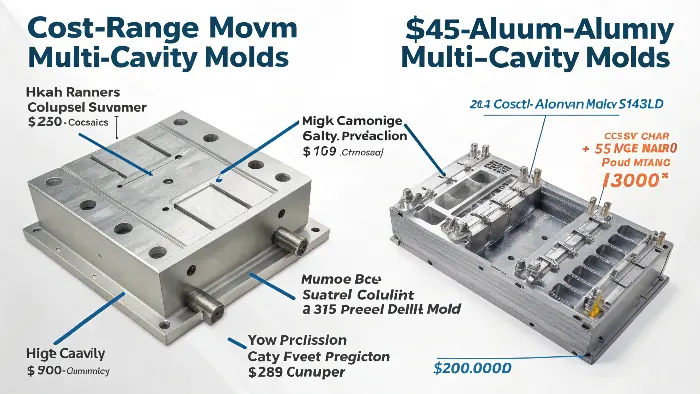
Multi-Cavity, Family and Separate Molds Compared
| Decision factor | Same-part multi-cavity | Family mold | Separate molds |
|---|---|---|---|
| Demand | Best considered when one part has stable, repeat demand | Useful when different components are consumed in a predictable ratio | Best when volumes or service demand differ |
| Material | One resin and color per shot | Parts must accept the same resin, color and preparation | Each part can use its own material and process |
| Filling and packing | Runner and cavity balance must keep each cavity within an acceptable window | Unlike geometries must share one fill, pack and pressure history | Gate and process can be optimized independently |
| Cooling and ejection | Cavities should reach release conditions consistently | The slowest or most difficult component can control the cycle | Cycle and ejection are independent |
| Inspection | Results should be identified by cavity | Each component and cavity position needs acceptance evidence | Inspection plans remain separate |
| Downtime | A mold stop removes all capacity for that part | One issue can stop several components | A problem in one mold does not stop the others |
| Engineering changes | A local correction must preserve balance | A change to one component can affect the shared tool | Revisions are isolated |
When a Same-Part Multi-Cavity Mold Makes Sense
Begin with demand and available production time. A screening estimate is:
Required cavities = annual good parts × cycle time ÷ planned production seconds ÷ expected yield.
Planned production seconds should exclude scheduled maintenance, changeover and known downtime. Yield should represent accepted parts. This estimate must then be checked against clamp force, shot size, mold footprint, hot-runner or cold-runner design, cooling, ejection, automation and inspection capacity.
Do not assume that doubling cavities halves cost. The tool may need a larger press, a more complex runner, additional hot-runner zones, tighter cavity matching and more maintenance. Unit cost improves only if the process produces balanced, acceptable parts at the expected uptime.

Why Family Molds Are More Difficult to Balance
Different parts can have different projected area, wall thickness, flow length, gate requirement, cosmetic standard, shrinkage behavior and cooling demand. The machine still provides one melt condition and one pressure sequence. A runner can distribute material, but it cannot make incompatible parts share an ideal packing or cooling window.
A family mold is a stronger candidate when:
- components use the same resin, color and conditioning;
- their demand ratio is stable and matches the parts produced per shot;
- fill, pack and cooling requirements are compatible;
- one component is unlikely to undergo frequent design changes;
- inspection can identify each part and cavity position; and
- the business accepts that one tool stop affects the whole set.
If one component has much lower demand, the excess becomes inventory or scrap. If one component controls the cycle, the other components wait in the mold. Both effects belong in the cost model.
Evaluate Quality by Cavity, Not by Average
A combined report can hide a weak cavity. Identify samples and measurements by cavity throughout T1, corrections and capability work. Review fill pattern, gate seal, pressure response, temperature, appearance, dimensions and ejection for each position.
For family tools, the acceptance plan should also link each component to its functional and cosmetic requirements. One stable part does not prove that another part in the same shot is capable.
Account for Maintenance and Continuity
More cavities increase the number of gates, vents, inserts, cooling circuits and moving interfaces that may need attention. The design should identify replaceable wear items and access for cleaning or repair. If production is critical, compare one large tool with modular inserts, duplicate tools or staged capacity. Maximum output from one tool is not the same as supply resilience.
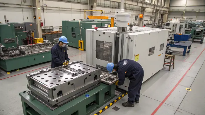
Use Risk-Adjusted Cost Instead of Tool Price Alone
Compare:
- tooling and hot-runner investment;
- press class and hourly conversion cost;
- cycle time, cavities, uptime and good-part yield;
- runner waste or regrind restrictions;
- inspection and cavity traceability;
- inventory imbalance for family parts;
- maintenance and spare components; and
- the cost of downtime or future product revisions.
Use the injection molding cost calculation guide to normalize the assumptions. For a same-part decision, also review the single- versus multi-cavity comparison.
Approval Checklist Before Mold Design Release
- Demand and service-part forecasts are documented for every part.
- Resin, color, drying and regrind rules are compatible.
- Runner, gate, packing and cooling assumptions are reviewed.
- The capacity model uses good parts, realistic uptime and inspection limits.
- T1 and production data will be identified by cavity and component.
- Downtime, maintenance and spare strategy are acceptable.
- Likely design changes have been considered before unlike parts are combined.
To review a specific cavity strategy, provide part files, resin, annual demand and target production location through the project requirements form. Send CAD separately to jerry@ckmold.com when available.