
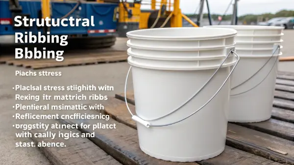
Ribs can increase a bucket wall’s bending stiffness without thickening the entire wall. Whether they allow a lighter bucket depends on the resin grade, load direction, geometry and service conditions. A design must still meet its filled-bucket drop, handle-load and sustained stacking requirements; adding ribs alone does not prove that it will.
Structural ribbing uses geometry to distribute loads and limit wall deflection. Place ribs along the relevant load paths, keep their roots from creating excessive local thickness, and check filling, cooling and ejection before reducing the nominal wall. Weight and cycle-time savings are design objectives to verify, not automatic results.
Understanding how ribs work is just the first step. You need to know exactly how to design them to get the best results. Let us look closer at why we use ribs and how to design them right.
What is the purpose of providing ribs on plastic parts?
For a bucket that deflects excessively, first identify the load case: lifting by the handle, carrying liquid, stacking filled containers or impact during handling. A rib arrangement that helps one load case can interfere with nesting, cleaning or another load path.
Ribs primarily increase bending stiffness by moving material away from the wall’s neutral axis. They can reduce deflection for a given mass, but stiffness, strength, impact resistance and long-term creep are different acceptance criteria. Check each criterion for the selected resin and finished geometry.
A side-wall panel may benefit from vertical ribs, circumferential ribs or a combination, depending on how it is loaded and supported. Compare candidate layouts with the same material and load assumptions rather than assuming that a few vertical ribs will solve every failure.
Weight and Cost Savings
Compare the mass of the complete ribbed design with the baseline, including the rim, handle attachments and base. A thinner wall can save material, but added ribs, a slower cycle or higher reject rates can offset that saving. Use the same load and appearance acceptance criteria for both designs.
Better Stress Handling
Ribs change the load path and can also concentrate stress at roots and intersections. Variable rib depth may help match local loads, but abrupt transitions can create weak regions. Check filled-bucket drops and handle loads at the intended service temperatures, and assess stacking creep over the required duration.
Here is a simple table to show what ribs achieve compared to thick walls:
| Feature | Thick Plastic Wall | Wall with Ribs |
|---|---|---|
| Material use | More material if the whole wall is thickened | May be lower if validated wall reduction exceeds added rib mass |
| Part weight | Depends on total volume and resin density | Compare the complete geometry at equal performance |
| Bending resistance | Increased by wall thickness | Depends on rib direction, depth and connections |
| Cooling time | Thick sections can govern the cycle | Thick roots or intersections can still govern cooling |
Ribs are useful when the structural benefit outweighs added molding complexity. They may be unsuitable on a required smooth cleaning surface, where nesting clearance is limited, or where the tooling cannot provide reliable filling and ejection.
What is the difference between a rib and a gusset?
People often mix up ribs and gussets in part design. This mistake can cause parts to break at the corners. Weak joints lead to broken buckets and unhappy buyers. You must know the difference to pick the right support feature for your product.
A rib is a raised ridge that strengthens flat or slightly curved walls, while a gusset is a specific type of rib used to support standing structures like bosses or walls at a 90-degree angle. Ribs run along a surface to stop it from bending. Gussets act like triangular braces connecting two different surfaces. Both use thin plastic to add strength, but ribs support open areas, and gussets reinforce corners and joints.
Choose the feature from the load path: a broad panel needs distributed stiffness, while a local attachment may need a brace connecting it to a supporting wall.
Understanding Ribs
Ribs stiffen broad flat areas. You use them on the main body of the bucket. You put them on the side walls or the bottom base. They run along the surface. They keep the large flat area from bending in or out. Modular rib designs let you change the pattern based on the industry. A paint bucket might need a different rib pattern than a food bucket. The rib pattern must be checked against those particular loads.
Understanding Gussets
Gussets have a very different job. Think of a gusset as a corner brace. If your bucket has a flat bottom and a straight side wall, the corner takes a lot of stress. A gusset bridges that 90-degree corner. It can reduce local deflection, but its root and adjacent wall still need a stress and molding review. We also use gussets to support tall features like screw bosses. A tall post can concentrate bending stress at its base; an appropriately placed gusset may help distribute that load.
Here is a breakdown of their differences:
| Feature | Structural Ribs | Gussets |
|---|---|---|
| Main Job | Stop flat walls from flexing | Brace corners and tall features |
| Location | Flat areas, side walls, bottoms | 90-degree joints, corners, bosses |
| Shape | Long raised lines or grids | Triangular or angled blocks |
| Force Type | Bending force | Snapping or pushing force |
Both features can distribute material efficiently. Not every bucket needs both: use ribs and gussets only where the load path, cleaning requirements, nesting clearance and mold construction support them.
What is the formula to calculate rib thickness in the rib design of a plastic part?
There is no universal rib-thickness formula that guarantees a sound bucket. An overly thick root can cause sink or internal voids; an overly thin or deep rib may be difficult to fill and eject. Start with the selected resin supplier’s part-design guidance, then validate the complete geometry.
Express a trial rib base thickness as t_r = k × t_w, where t_w is the nominal wall thickness and k is a starting ratio chosen for the resin grade, surface requirements and processing conditions. Neither a ratio nor the wall thickness alone establishes acceptable strength or appearance. For an illustrative calculation only, k = 0.5 and t_w = 2.0 mm give t_r = 1.0 mm; this is not a validated bucket specification.
Record the selected grade, nominal wall, rib-base thickness, root radius, draft and relevant acceptance tests in the design review. This makes the assumptions traceable when trial results require a geometry change.
The Danger of Thick Ribs
If you make a rib as thick as the main wall, you create a big problem. The plastic becomes very thick where the rib meets the wall. This thick spot cools slowly. When plastic cools, it shrinks. The inner plastic pulls on the outer surface. This creates an ugly dent called a sink mark. Thick ribs also cause stress concentrations and ejection problems. The part might stick in the mold. You lose time and money.
Selecting and Checking the Starting Geometry
The resin grade, visible surface opposite the rib, packing conditions and local junction geometry matter more than a generic high-shrink/low-shrink table. Review the thickest combined section at the root and intersections. BASF's injection-molding design guidance explains how material accumulations can increase the risk of voids, shrinkage and warpage. A geometry check or simulation identifies risk; molded samples establish whether the proposed part meets its requirements.
Adding Draft and Fillets
Draft should follow the pull direction and account for rib depth, surface texture, resin shrinkage and ejection method. Check the remaining rib-tip thickness after draft is applied. Round the root to reduce stress concentration, but avoid a radius so large that it creates a heavy junction and cooling hotspot. Agree the geometry with the mold designer rather than applying one draft angle or an unlimited fillet to every rib.
What are the main design considerations for injection molding ribs?
Bad rib design can destroy your injection molding process. Plastic might freeze before filling the rib. Air might get trapped inside. These errors waste costly materials and halt your production line. You must plan your ribs carefully to keep the molding process smooth and profitable.
Review placement, height, root thickness, draft, flow direction, venting and ejection as one system. Several shallower ribs may be easier to mold than one deep rib, but spacing, intersections and required stiffness still control the choice. Include the rib pattern in a DFM review before committing to the tool layout.
Designing ribs is not just about making the part strong. It is also about making the part easy to build. The design must respect the injection molding process. Let me share how we do this.
Strategic Placement
Ribs work best where loads concentrate on a bucket. You should focus on the bottom transitions, corners, lifting points, and handle attachment zones. These areas take the most force. By targeting these zones, a rib pattern can let you use a thinner base wall while preserving performance.
Deep Ribs vs Short Ribs
Deep, thin ribs can be difficult to fill and vent, and can increase demolding resistance. Compare several shallower ribs with a deeper alternative using the actual flow length, resin and mold layout. More ribs are not automatically better: intersections add material and can restrict cooling access.
Advanced Planning Tools
Structural analysis can compare deflection and stress under specified loads; filling, packing and cooling analysis addresses different manufacturing questions. Check the model assumptions, then confirm the design with molded samples. A visually appealing honeycomb or other pattern is not evidence of adequate performance.
| Design Rule | What to Do | Why it Matters |
|---|---|---|
| Rib height | Balance stiffness with filling, venting and ejection | A height ratio alone does not prevent short shots |
| Rib spacing | Review steel strength, intersections and the actual cooling layout | A spacing ratio does not guarantee room for cooling channels |
| Rib roots | Use a suitable radius without excessive local thickness | Balance stress concentration against sink and cooling risk |
| Rib draft | Review depth, texture, material and pull direction | Check release and the remaining tip thickness |
Before approval, compare baseline and revised buckets for mass, critical dimensions, nesting, filled drops, handle attachment loads and sustained stacking. Define contents, fill mass, temperature, test duration and pass/fail limits with the buyer. Reinforced or alternative resins require a separate review of impact behavior, shrinkage and any applicable contact requirements.
Conclusion
Use ribs to place material where it contributes to stiffness, while controlling roots, intersections, filling and ejection. Release a lighter design only after it meets the same agreed service and manufacturing requirements as the baseline. For a bucket DFM and quotation, provide the CAD revision, resin grade, fill mass, handle and stacking loads, nesting requirements, appearance limits and intended production volume.