
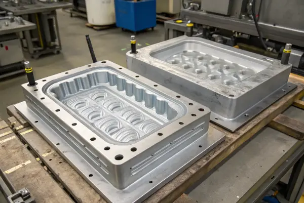
The objective is a repeatable temperature distribution and an ejectable container that meets flatness, lid fit, appearance and load requirements. More channels, colder water or a printed insert do not guarantee a shorter acceptable cycle. First identify which region and which failure mode limit the current process.
What Are the Core Design Principles for Mold Cooling Channels?
Retain the useful aim of bringing coolant near the heat source, but establish the minimum steel ligament from cavity pressure, tool loading, steel condition, cross-drilled intersections and nearby ejectors or fasteners. A close channel can create a weak section or a local cold band. Check the complete geometry rather than using the smallest possible distance everywhere.
Choose diameter and spacing together
There is no general rule that many small channels outperform fewer larger ones. Compare heat-transfer area with achievable flow, pressure loss, cleaning access and blockage risk. Autodesk’s cooling-channel pressure-drop guidance identifies longer paths, higher velocity and smaller diameter as factors that raise pressure requirements. A pump-pressure reading alone does not establish the flow through each circuit.
Balance the container’s heat load
Review the broad walls, base, rim, corners, handles and local ribs separately. Core and cavity sides may need different circuit layouts and settings to produce an acceptable thermal balance. Do not infer the direction or amount of warpage from a single hot-side rule; resin behavior, geometry, packing and fiber orientation can also matter.
| Design choice | Useful aim | Condition to check |
|---|---|---|
| Channel distance | Shorten the conduction path | Steel ligament, local temperature variation and interference |
| Diameter and spacing | Serve the local heat load | Flow, pressure drop, fouling and service access |
| Consistent flow area | Avoid unnecessary restrictions | Fittings, turns, manifolds and local cooling devices |
| Core/cavity balance | Control differential cooling | Measured part shape and surface temperatures at a repeatable cycle point |
Autodesk’s cooling-system design considerations treats coolant properties and mechanical constraints as part of the design. Use simulation to compare candidates, then confirm the relevant temperatures and molded result during trials.
How Do We Choose the Right Flow Layout for Large Molds?
Select the circuit layout after documenting the water or coolant mixture, operating temperature, available supply/return pressure and flow at the molding machine. Include hoses, quick couplings, manifolds, filters and temperature-control equipment in the hydraulic assessment.
Series circuits
A series circuit carries the same flow through its connected sections, which can simplify verification. It does not create turbulent flow merely by being long. Excessive length can consume the available pressure and reduce flow. Split a large tool into manageable circuits when a single loop cannot meet its thermal and hydraulic requirements.
Parallel circuits
Parallel branches share the available supply. Their flow depends on individual resistance; adding branches does not create additional pump capacity. Measure and balance each branch, and define how a restricted branch will be detected. Review both branch performance and the common supply.
Multiple zones
Separate zones can serve the base, walls and rim or deep core when their loads differ. Give every circuit a durable identifier, inlet/outlet label, flow requirement and maintenance access. Choose the number of zones from the geometry and utility capacity, not container size alone.
| Layout | When to evaluate it | Release evidence |
|---|---|---|
| Series | A connected path within the available pressure and temperature-rise limits | Measured circuit flow and inlet/outlet conditions |
| Parallel | Several regions need service and a long series path is impractical | Individual branch flow and balancing record |
| Multiple controlled zones | Different regions need separate thermal control | Zone settings, sensor locations, alarms and repeatable part results |
The Autodesk comparison of series and parallel circuits explains the flow-distribution and pump-capacity tradeoffs. Set project limits for coolant temperature rise and pressure loss; do not adopt a generic circuit length or assume that equal inlet temperatures mean equal cooling.
How Do We Solve Cooling Issues in Large Container Molds?
Keep the original focus on broad walls, deep cores and thick intersections. Confirm the hot region before selecting a device. A local cooling change should be evaluated against the complete container, including ejection distortion and dimensions after the agreed conditioning period.
Broad walls and deep cores
Use channel coverage appropriate to the wall geometry and heat load; equal spacing is a starting layout, not a universal acceptance rule. A bubbler places a tube inside a larger hole so coolant can travel through the tube and return through the surrounding passage. A baffle divides a hole so coolant travels along one side and returns along the other. Verify the actual flow direction, clearances, sealing and pressure loss.
Distinguish heat pipes from solid conductive inserts
A thermal pin may refer to a sealed heat-pipe device, not simply a solid metal rod. DME’s heat-pipe guidance describes a sealed device that transfers heat to a cooler region and must remain within its specified operating conditions. Follow its installation instructions; do not machine it as if it were an ordinary core pin.
A copper-alloy insert conducts heat through the material and its interfaces to a heat sink. Its value depends on the selected alloy, contact, available sink and mechanical duty. Check wear, strength, fit and differential thermal expansion; DME’s performance core-pin guidance illustrates why an operating fit cannot be copied directly from a steel assembly.
| Candidate | Purpose | Key check |
|---|---|---|
| Bubbler or baffle | Circulate coolant in a difficult core region | Flow path, return area, sealing, pressure loss and cleanability |
| Heat pipe | Transfer heat to a cooler region without circulating water at its hot end | Supplier limits, orientation, contact and cold-end capacity |
| Conductive insert | Improve a local conduction path | Alloy properties, thermal contact, wear and operating fit |
When Should You Use Conformal Cooling for Molds?
Evaluate conformal cooling when drilled channels and conventional local devices cannot adequately serve a critical region within the available space and pressure budget. Contoured or spiral passages may improve access, but their length, roughness and return path can also increase resistance. A spiral is a geometry option, not evidence of uniform temperature.
A hybrid tool can combine conventional drilled blocks with a local conformal insert. Compare the proposed route with a serviceable conventional alternative. For a metal powder-bed printed insert, include material qualification, powder removal, heat treatment, machining, leak testing and internal-passage inspection in the manufacturing plan. EOS’s metal manufacturing periphery overview shows why powder handling and finishing remain part of the production chain.
| Route | Potential fit | Cost and acceptance boundary |
|---|---|---|
| Drilled circuits with local devices | Accessible walls and cores | Machining, plumbing, maintenance and proven hydraulic performance |
| Local conformal insert | A difficult region that limits the accepted cycle | Manufacturing, finishing, inspection, replacement and measured benefit |
| Spiral passage | A suitable curved feature | Pressure loss, temperature rise and the complete return path |
Estimate payback from accepted parts per hour, realistic operating hours, scrap, energy and maintenance. Do not promise a fixed cycle reduction or rapid payback without comparative trials. For a deeper review of the manufacturing and hydraulic limits, see conformal cooling design and qualification.
How Can We Optimize Cooling with Advanced Tools and Materials?
Use thermal and coolant-flow analysis where it can resolve a design decision. Record resin data, geometry, cycle definition, coolant properties, heat-transfer assumptions and the modeled circuit. A CFD color map alone does not validate a production mold. Compare predictions with measured conditions at defined cycle times and update the model when the trial differs.
Sensors provide information; automatic control additionally requires a defined controller, valves or pump strategy, suitable sensor placement and fault handling. Confirm what the installed equipment actually measures and controls. Do not infer continuous perfect temperature from the presence of a sensor.
| Trial check | Record | Decision supported |
|---|---|---|
| Hydraulic performance | Flow and inlet/outlet temperature and pressure for each labeled circuit | Whether the design operates within the available utilities |
| Thermal repeatability | Measurement location, method and cycle point after stabilization | Whether the critical hot region and core/cavity balance are controlled |
| Product acceptance | Conditioned flatness, dimensions, lid fit, appearance and required load/leak tests | Whether the proposed cycle produces acceptable containers |
| Production durability | Leak checks, flow baseline, cleaning access and restricted-flow response | Whether performance can be maintained after handover |
For an RFQ or DFM review, provide part CAD, wall/rib details, resin grade, target cavity count, original and proposed cycle assumptions, plant coolant data, available controllers and the container acceptance criteria. Ask the supplier to separate calculated predictions from measured trial results. Use mold testing and validation to agree the release records before accepting a cycle-time claim.
Conclusion
Choose cooling circuits from the container’s local heat load, tool geometry and available utilities. Use local cooling devices or conformal inserts where they solve a demonstrated limitation, then release the tool against measured flow, thermal repeatability and acceptable molded containers. Keep the circuit drawing, trial conditions and maintenance baseline with the mold.