
Are you struggling with TPE over-molded parts that peel, separate, or fail under stress? This common problem can lead to product recalls, wasted materials, and a loss of customer trust. You might be wondering if achieving that seamless, permanent bond is even possible. The key is understanding that a successful bond isn’t magic; it’s a science that combines material chemistry, smart design, and precise process control to create an inseparable connection.
A reliable TPE overmold is created at the interface, not simply on the surface of the substrate. The selected TPE, substrate grade, surface condition, temperature history, pressure, venting, shrinkage and mechanical retention all determine whether the finished part peels, shifts, flashes or survives service. A strong design distinguishes chemical adhesion from mechanical interlock and validates the actual material pair.
Related engineering resources: insert molding and overmolding | mold testing and validation | mold design
To master TPE over-molding, you must focus on three core principles. First, ensure chemical compatibility by selecting a TPE grade and a rigid substrate that can form a strong molecular bond when melted together. Second, design the rigid part with mechanical interlocks like undercuts, shut-off grooves, or through-holes that physically anchor the TPE. Finally, you must optimize your injection molding process parameters, especially melt temperature and injection speed, to promote a complete and permanent fusion between the two materials.
Getting that consistent bond is the ultimate goal in any over-molding project. It’s what separates a premium product from a cheap imitation. This bond doesn’t just happen by chance; it’s the result of two types of adhesion working together: chemical bonding and mechanical interlocking. A chemical bond is a molecular-level fusion between the two materials, while a mechanical bond is a physical connection, like a key in a lock. To achieve true mastery, you need both.
Why Is Material Selection The First Step To a Suitable TPE Bond?
Have you ever picked a high-quality TPE and a durable substrate, only to find they refuse to stick together? It’s a frustrating experience that can make you question your entire process and material choices. You start to think your project is impossible. The reality is that material compatibility isn’t about quality alone; it’s about chemistry. Understanding which materials work together is the first and most critical step toward creating a bond that is unlikely to fail.
Material selection is crucial because the strength of a TPE over-mold bond primarily relies on chemical compatibility. For a powerful molecular bond to form, the TPE and the rigid substrate must have similar chemical structures and polarity. For instance, styrenic-based TPEs (TPE-S) bond exceptionally well to non-polar plastics like polypropylene (PP). In contrast, polar materials like ABS or PC require polar TPEs, such as thermoplastic polyurethane (TPU) or copolyester (COPE), to achieve strong adhesion. Choosing incompatible materials helps support a weak bond, no matter how suitable your design or process is.
The success of your over-molding project is often decided before the mold even closes. It’s decided when you choose your materials. Think of it like trying to mix oil and water—if the fundamental chemistries are incompatible, they is unlikely to truly combine. The same principle applies to plastics.
Understanding Chemical Polarity
At the molecular level, plastics are either “polar” or “non-polar.”
- Polar plastics like ABS, Polycarbonate (PC), and Nylon have an uneven distribution of electron charges in their molecules.
- Non-polar plastics like Polypropylene (PP) and Polyethylene (PE) have an even charge distribution.
For a strong chemical bond, you must match polar TPEs with polar substrates and non-polar TPEs with non-polar substrates. This “like-attracts-like” rule is non-negotiable. Trying to bond a non-polar TPE-S to a polar PC substrate without a special adhesion promoter is a recipe for failure.
TPE and Substrate Compatibility Chart
To make this easier, here is a quick reference table. I’ve used this countless times to guide clients in making the right choice from the start.
| TPE Type | Common Name | Compatible Substrates | Bond Quality |
|---|---|---|---|
| TPE-S (SEBS/SBS) | Styrenic | PP, PE, PS, TPO | Excellent |
| TPU | Polyurethane | ABS, PC, PC/ABS, PMMA | Excellent |
| TPV | Vulcanizate | PP, EPDM | Excellent |
| COPE (TPE-E) | Copolyester | PC, PBT, PETG, ABS | Excellent |
| COPA (TPE-A) | Copolyamide | PA6, PA66 (Nylon) | Excellent |
Remember, this is a starting point. Generally consult the material supplier’s datasheet. They provide specific bonding information for their grades, and some companies have developed special TPE formulations that can bridge the compatibility gap and bond to substrates they normally wouldn’t.
How Can Part Design Create An Unbreakable Mechanical Lock?
You’ve selected chemically compatible materials, yet you’re still not getting the robust bond your product requires for long-term durability. The chemical bond is good, but it might not be enough to withstand the prying, twisting, or pulling forces of real-world use. It’s disheartening when a part that looks suitable fails under physical stress. This is where clever part design transforms a good bond into an unbreakable one by adding a physical, mechanical connection.
To create an unbreakable mechanical lock, your part design must incorporate features that physically restrain the TPE, preventing it from peeling or separating from the hard substrate. This is achieved through strategic design elements like undercuts, shut-off grooves, or through-holes. These features allow the molten TPE to flow into and solidify within the substrate, forming a solid mechanical interlock. This physical connection works in tandem with the chemical bond to create a bond that can withstand significant force, ensuring product integrity and longevity.
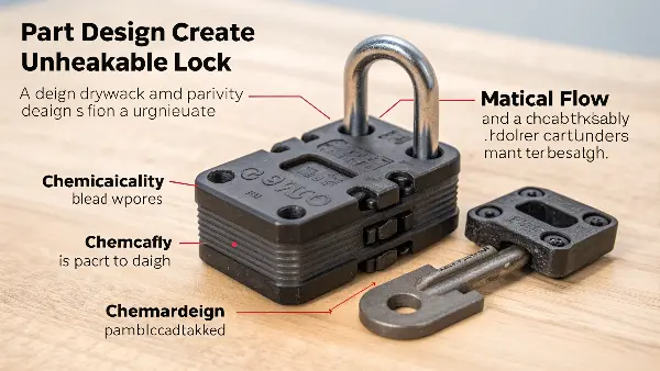
Key Mechanical Interlocking Features
Design Guidelines for Mechanical Interlocks
| Feature | Design Recommendation | Why It Works |
|---|---|---|
| Shut-off Groove | Minimum depth and width of 1mm. Place around the over-mold perimeter. | Prevents the TPE from peeling up at the edges, which is the most common failure point. |
| Through-Holes | Diameter should be at least 1.5 times the TPE wall thickness. | Creates a strong TPE rivet, locking the material from both sides of the substrate. |
| TPE Thickness | Maintain a minimum thickness of 1.5mm to 2mm. | Ensures there is enough material mass to create a durable-feeling part and fill features. |
| Sharp Corners | Avoid sharp internal corners on the substrate; use generous radii instead. | Prevents stress concentration points and helps the TPE material flow smoothly. |
By incorporating these features, you are no longer just gluing two surfaces together; you are physically weaving them into one another. This dual-pronged approach of chemical and mechanical bonding is the secret to creating TPE over-molded parts that last.
What Are The Critical Mold Design Features For consistent Over-molding?
Your materials are compatible and your part design includes strong mechanical locks. However, during production, you’re experiencing issues like flash, incomplete filling, or damage to the substrate inserts. Your operators struggle with inconsistent quality, slowing down production and increasing scrap rates. These problems often point not to the part, but to the tool itself. An improperly designed mold can undermine even the best material and part design choices, making consistent execution impossible.
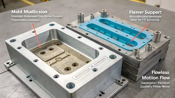
A successful over-molding mold must be designed for precision, stability, and efficient TPE flow. Critical features include robust insert support to prevent the substrate from shifting or deforming under high injection pressure. The gating strategy is also key; gates should be placed to direct TPE flow across the bonding surface without causing substrate erosion. Finally, effective venting is essential to allow trapped air to escape, preventing short shots and ensuring the TPE cavity fills completely for a suitable, void-free bond.
Core Principles of Over-molding Mold Design
-
Gating Strategy:
Where and how you inject the TPE is critical. The gate location determines how the material flows over the substrate.- Tab Gate: Often preferred because it creates a wide flow front that gently pushes air out.
- Submarine (Tunnel) Gate: Good for automatic de-gating but can create high shear.
The goal is to gate in a way that maximizes adhesion without dislodging the insert or causing cosmetic defects on the final part. Avoid gating directly onto a small, delicate area of the substrate.
By focusing on these mold design principles, you create a robust and repeatable process, turning the potential for defects and inconsistency into a reality of high-quality, reliably bonded parts, cycle after cycle.
How Do You Optimize Processing For The Strongest Possible Bond?
You have the right materials, a smart part design, and a precision mold. Yet, your parts are inconsistent. Some have a suitable bond, while others can be peeled apart with little effort. This inconsistency is maddening and can point to a process that isn’t properly dialed in. Simply having the right tools isn’t enough; knowing how to use them is essential. Optimizing your injection molding processing parameters is the final, critical step to ensuring a strong, reliable bond every single time.
To optimize the TPE over-molding process, you must carefully control temperatures, pressures, and speeds to promote ideal bonding conditions. The most critical parameter is the TPE melt temperature; it must be high enough to reactivate the surface of the hard substrate, allowing the two materials to fuse at a molecular level. Maintaining sufficient injection pressure and hold time ensures the TPE cavity is fully packed out, maximizing surface contact. Furthermore, minimizing the time between molding the substrate and over-molding it keeps the substrate warm, which significantly enhances the chemical bond.
Think of the injection molding machine’s control panel as a chef’s stove. You can have the best ingredients (materials), the best recipe (design), and the best cookware (mold), but if your temperatures and times are wrong, you’ll ruin the dish. Processing is where we fine-tune the interaction between the TPE and the substrate. The goal is to get the TPE hot enough to create a molten interface with the substrate’s surface. This brief moment, when both surfaces are in a melt state, is where the chemical bond forms. A difference of just 10 degrees Celsius can be the difference between a weak bond and one that is stronger than the TPE itself.
Key Processing Parameters to Control
To achieve a consistently strong bond, focus on dialing in these four areas. I generally start with the material supplier’s recommendations and then adjust based on the specific part and mold.
A Typical Optimization Process
| Parameter | Setting | Reason |
|---|---|---|
| Drying TPE | Yes, per supplier specs | Removes moisture which can cause splay and degrade bond quality. |
| Melt Temperature | Upper end of recommended range | Maximizes thermal energy for fusing with the substrate. |
| Mold Temperature | 25°C – 60°C | Controls cooling rate and part aesthetics. |
| Injection Speed | Fast, but not to the point of flash | Gets hot material to the bond interface quickly. |
| Hold Pressure | 40-60% of injection pressure | Ensures maximum surface contact during cooling. |
By systematically controlling these variables, you move from “hoping” for a good bond to “engineering” one. This level of process control is what separates amateurs from masters in the world of TPE over-molding.
Confirm Compatibility Before Cutting Steel
List the exact TPE grade and the substrate resin, filler, color and surface treatment. A material family name is not enough because additives and processing grades can change adhesion. Review temperature limits and likely exposure to oils, cleaners, UV, sweat, humidity or thermal cycling.
Use Geometry to Support the Interface
Ribs, holes, grooves, dovetails, windows and wrap-around features can provide mechanical retention when chemical bonding is uncertain. Avoid sharp substrate edges that concentrate peel stress or create thin TPE coverage. Design stable datums so the substrate is located consistently in the second shot.
Control the Thermal State of the Substrate
The substrate must be hot enough, clean enough and supported well enough for the TPE to wet or lock onto it without distortion. Transfer time, preheating, insert temperature and cavity contact affect the interface. Record these conditions during trials instead of treating them as operator preference.
Balance Flow, Pressure and Flash
The TPE should reach the interface with a predictable front and enough pressure to fill the intended area, but excessive pressure can shift the insert or force flash through a shutoff. Gate placement, overflow, vents, clamp support and local steel strength should be designed as one package.
Test Bond Strength in the Direction of Use
Peel, pull, torsion, compression, flexing and thermal cycling expose different weaknesses. Test after conditioning and after relevant chemical or humidity exposure. Record failure mode—adhesive separation, cohesive tear, substrate failure or mechanical pullout—because the corrective action depends on what actually failed.
TPE Overmolding for a Reliable Bond: Buyer Review Checklist
- Confirm exact TPE and substrate grades, additives and service environment.
- Choose chemical bonding, mechanical retention or a deliberate combination.
- Design substrate location, support, surface preparation and transfer temperature.
- Control gate, vent, overflow, pressure, shutoff and insert movement.
- Test bond strength and failure mode after realistic conditioning and aging.
Frequently Asked Questions
Can every TPE bond to every plastic substrate?
No. Compatibility varies by exact grade and surface condition. When chemical adhesion is uncertain, use mechanical retention and verify the finished interface with application-specific tests.
What does a good overmold bond test report include?
It should state specimen geometry, direction and speed of loading, conditioning, peak load, failure mode and whether the result meets the product requirement.
Conclusion
Mastering TPE over-molding is not about a single secret trick. It’s about a holistic approach that meticulously integrates four key pillars: choosing chemically compatible materials, embedding mechanical locks into your part design, engineering a precision mold, and fine-tuning your processing parameters. By ensuring these elements work in harmony, you can transform the challenge of bonding soft TPE to hard substrates into a reliable, repeatable process for creating high-quality, durable, and inseparable products.