
CKMOLD’s venting-system approach is built around the complete gas path rather than a single vent feature. The engineering review connects part geometry, flow analysis, resin condition, gate and runner design, vent location, mold strength, flash risk, trial evidence and maintenance. The objective is not to claim that every air-related defect can be eliminated by venting alone, but to make the cause, design decision and validation evidence clear.
Related CKMOLD resources: mold design, DFM analysis, mold testing and validation.
A robust design identifies where cavity air and material gases travel, gives them a controlled path out without flash, and provides access for measurement, cleaning and maintenance. Simulation is one input and must be correlated with trial evidence.
What Defects Can Inadequate Mold Venting Produce?
Compressed cavity gas can contribute to burns, short shots, weak or visible weld lines, hesitation and unstable filling. Similar symptoms can also come from degradation, moisture, temperature, runner/gate restriction or machine conditions, so location and timing must be checked before changing the vent.
- Burn near end of fill: compare air-trap location, vent condition and fill speed with material degradation evidence.
- Short shot: separate trapped-gas resistance from insufficient volume, pressure, temperature or a frozen restriction.
- Weak/visible weld: review flow-front location, temperature, pressure, filler orientation and whether gas can escape.
- Flash at a vent: measure vent depth/land, parting-line support and peak cavity pressure before closing the entire gas path.
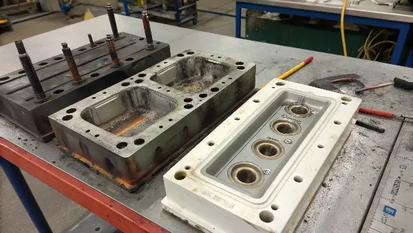
Illustrative scenes; they are not measured defect samples, validated simulation output or records of a specific CKMOLD project.
Important Guidelines for Designing an Effective Venting System
Trace the complete gas path from the cavity to atmosphere. Identify last-fill regions and gas-generating mechanisms, then select parting-line, insert, ejector, overflow or other vent routes that the tool can support and maintain.
- Map predicted air traps against short-shot, burn, weld-line and pressure evidence.
- Specify the vent entrance, land and relief for the exact resin and flash limit; do not copy one universal depth.
- Keep a continuous exit path beyond the cavity and avoid shutoffs or deposits that trap gas downstream.
- Provide steel support, access for measurement and cleaning, and a documented reinspection method.
Release the vent design only after a controlled molding trial confirms acceptable fill, appearance and function without unacceptable flash across the agreed process window.
How Does Mold Flow Analysis Guide Our Venting Strategy?
Flow simulation can identify candidate air-trap locations from the model and process assumptions. Compare predictions with short shots, defect maps and measured process response; simulation cannot remove uncertainty or guarantee a defect-free part.
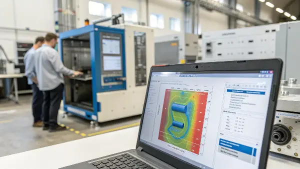
From Simulation to Reality
Use the mold-flow report to prioritize locations for physical vent review and trial confirmation.
- Fill Time Animation: We watch a virtual animation of the mold filling. This shows us the path the plastic takes and, more importantly, where the last fill points are. These are natural locations for air to be trapped, and are prime candidates for vents.
- Air Trap Analysis: Treat predicted locations as candidates. Check mesh, material and process assumptions, then verify the location against fill evidence and a feasible gas path, steel support and maintenance access.
- Weld Line Prediction: Compare predicted flow-front meetings with the real part’s appearance and strength requirements. Venting can address trapped gas, but does not independently establish weld-line strength.
A vent-design review can be organized into these stages; request the actual records for the proposed project:
| Stage | Action Taken | Benefit |
|---|---|---|
| 1. Simulation | Run mold flow analysis on the 3D part model. | Predicts fill pattern, pressure, and air traps. |
| 2. Analysis | Identify candidate air-trap and weld-line locations under the recorded model assumptions. | Creates a candidate map for physical review and trial confirmation. |
| 3. Design | Integrate vents of the proper type and size into the mold design. | Provides a proposed path whose continuity, flash limit and maintenance access must be checked. |
| 4. Manufacturing | Machine the vents into the mold steel with high precision. | Turns the data-driven design into a physical reality. |
This strategy transforms venting from a reactive fix into a proactive, engineered solution.
What Are The Different Types Of Vents We Use In Our Molds?
Select the physical vent route for the local gas trap. A parting-line vent uses a shallow entrance land followed by an escape path. Vented pins or inserts can serve regions away from the split. Porous metal may provide distributed gas release, but resin intrusion, surface witness, finishing and cleaning depend on the particular product and operating conditions.
For a deep pocket or rib remote from the parting line, review an insert or ejector vent path and its access for cleaning. Qualify the proposal against flash and part requirements rather than assuming a particular vent type will remove the defect.
Choosing the Right Vent for the Job
The selection of a vent isn’t random; it’s a calculated decision based on the mold’s design and the insights from our mold flow analysis. Each type has its advantages and is suited for different situations.
- Parting Line (Perimeter) Vents: This is the most common and fundamental type. It’s a shallow channel (the “vent land”) cut from the edge of the cavity to the outside of the mold on the parting line. The depth is critical—deep enough for air, but too shallow for plastic to flow through. It’s great for venting the general perimeter of a part.
- Vent Pins: When an air trap is predicted in an area far from the parting line, we use an ejector pin or a dedicated pin and grind a small flat on its side. This flat creates a tiny channel for air to escape along the pin and out the back of the mold. It’s an ingenious way to vent isolated hot spots.
- Porous Mold Inserts: Check supplier guidance for resin compatibility, porosity, surface finishing, gas-path connections and cleaning. Gas permeability depends on the insert and operating conditions; it is not simply a molecular-size filter that guarantees exclusion of molten polymer.
Here is how we decide which to use:
| Vent Type | Best Use Case | Key Advantage |
|---|---|---|
| Perimeter Vent | Around the main outline of the part. | Simple to machine, effective for general venting. |
| Vent Pins | Deep ribs, bosses, or isolated air traps. | Vents areas that are unreachable by the parting line. |
| Porous Inserts | Large, flat cosmetic surfaces or fast-filling parts. | Can provide distributed venting; assess surface witness, clogging, cleaning and resin compatibility. |
Specify Vent Dimensions From the Actual Resin and Tool
Use the resin grade, local flow and pressure, flash limit and available steel support to specify the vent entrance, land and relief path. A generic material-family depth table is not a released drawing.
Correlate predicted last-fill locations with trial evidence, measure the as-built path and retain conservative steel-safe adjustment where feasible. Confirm the route to atmosphere, cleaning access and acceptable part witness before approval.
Why Is Vent Maintenance Just As Important As The Initial Design?
If burns, short shots or weld-line symptoms return, compare vent condition and the current material/process record with the accepted baseline. Deposits or a restricted exit path may contribute, but confirm the cause before cleaning or changing vent dimensions.
Outgassing is the release of gas or volatile material; it is not the name for every deposit. Resin or additive residue, degradation products, release agents, oils and debris can restrict a vent. Identify the actual contaminant and approved cleaning method, then verify the restored gas path and part result.
A Simple but Critical Process
Set the maintenance method and interval from the vent design, resin and additive system, operating history and measured condition. Porous inserts may require specialist cleaning and permeability checks under the supplier’s instructions.
Causes of Vent Clogging:
- Resin and additive deposits: Review the exact grade, thermal/residence history and observed deposit. Some material systems can produce corrosive or persistent contamination; do not assign one behavior to all flame-retardant or PVC formulations.
- Mold Release Agents: Over-spraying mold release can also lead to build-up that clogs the vents.
- Material Dust and Debris: Small fines or dust from the plastic pellets can be carried into the mold and deposited in the vent channels.
A Proactive Maintenance Schedule:
Agree condition-based inspection and cleaning triggers for the actual tool. The table identifies the evidence and release checks; it is not a universal daily or weekly schedule.
| Trigger | Action | Release evidence |
|---|---|---|
| Agreed production inspection point or changing defect trend | Inspect accessible vent entrances and the downstream exit path under the approved safe-access procedure. | Vent ID, deposit/wear condition and comparison with accepted parts |
| Measured or observed restriction | Follow the mold maker’s approved cleaning and isolation procedure. Protect the land and shutoff from dimensional change. | Before/after condition and dimensions where material removal could occur |
| Tool pull or porous-insert service | Use the component supplier’s removal, cleaning and restoration method; do not assume one solvent or ultrasonic process fits every insert. | Restored flow/permeability, reassembly and controlled molding verification |
For porous components, DME’s Vortex/Porcerax application guide describes resin, finishing, contamination and professional-cleaning limitations. Use the current instructions for the exact supplied product; this example is not a cleaning procedure for every porous insert.
Separate the evidence used to locate a gas trap from the tool detail used to release it: review venting-focused Moldflow analysis, then specify the physical path with the vent location, sizing and maintenance guide.
Maintain and Verify the Gas Path
Set cleaning intervals from resin deposits, vent measurements and defect trends rather than a universal calendar. The maintenance record should identify vent location, depth/land before and after service, cleaning method, material removed, nearby part witness and the trial result. Protect precision parting surfaces; aggressive polishing can deepen a vent or round a shutoff.
At handoff, request the vent map, dimensions, approved cleaning method, replaceable vent components and the short-shot/pressure evidence used to approve the design.
Use a Vent-Design Evidence Package
Combine fill/air-trap simulation with short shots, cavity-pressure or process traces and visible defect maps. Autodesk describes air-trap output as a probability/risk result; the model and vent assumptions must be correlated with the real tool. Release dimensions only after the exact resin runs without unacceptable flash or trapped-gas symptoms across the agreed process window.
Technical references: Autodesk Moldflow — Air Trap Result (interpretation of predicted air-trap locations); DME — Venting Solutions (mold-vent design and maintenance options). Apply the cited scope to the exact grade, tool and acceptance plan.
Start With Flow and Function
Identify cosmetic surfaces, structural weld lines, last-fill regions, inserts, ribs, deep pockets and sealing features. A vent decision is prioritized by the consequence of trapped gas and the accessibility of the location, not simply by how easy it is to cut a vent.
Combine Simulation With Tool Experience
Use Mold Flow or a comparable review to predict air traps and flow-front meetings, then apply practical knowledge of parting, ejectors, slides, inserts, steel strength and flash. Simulation narrows the risk; experienced tooling decisions convert it into manufacturable vent features.
Use Multiple Venting Mechanisms When Needed
Parting-line vents, ejector clearances, insert vents, porous steel, overflow wells or local vent details may be combined. Each mechanism is specified with its cleaning, wear, alignment and flash-control requirements. Avoid adding vents without understanding how they interact with the cavity and shutoffs.
Validate With a Repeatable Trial Method
Use short shots, controlled speed and temperature changes, burn and weld-line inspection, pressure or fill-time data, weight, dimensions and appearance checks. Record the result by cavity and tool revision. A correction is not complete until it works beyond a single sample.
Transfer the Knowledge Into Maintenance
Provide a vent map, cleaning instructions, inspection points, defect-response guidance and records. If a vent is cleaned, polished, deepened or repaired, the mold file should show the change and the next approval condition.
CKMOLD Venting System Design: Buyer Review Checklist
- Map air risk from geometry, function, flow, material and gate decisions.
- Combine simulation with parting, ejection, steel, flash and maintenance judgment.
- Select parting, ejector, insert, porous or overflow venting where appropriate.
- Validate with short shots, burn, weld-line, pressure, weight, dimensions and appearance data.
- Deliver a vent map and maintenance record that preserves the engineering decision.
FAQ
Can CKMOLD eliminate every air-related molding defect?
No supplier should promise that without understanding the part and process. CKMOLD can analyze gas risks and develop a validated venting and process-control strategy.
What should be included in a venting design review?
Review part and flow geometry, resin, gate, vent locations, flash, steel, ejection, trials, inspection and maintenance together.
Conclusion
Effective injection-mold venting provides a controlled route for cavity air and material gases while protecting the shutoff from flash. The released solution should connect the predicted gas risk, physical vent dimensions, trial evidence and a maintenance record.
For supplier review, provide the part geometry, exact resin and additives, cosmetic and functional zones, forecast volume and known defect evidence. Ask the supplier to return a vent map, critical dimensions, validation method and cleaning plan rather than an unsupported promise to eliminate every air-related defect.