
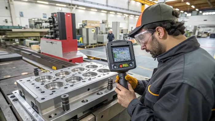
Struggling with warped plastic parts? It’s frustrating, costs you money, and delays projects. Effective cooling system design is your key to solving this.
Cooling is one of the most important systems in an injection mold because it controls both cycle time and the shape released from the cavity. A cooling layout that looks balanced on a drawing may still produce different heat-transfer performance if circuits are too long, flow is uneven, inserts are isolated or channels are too far from the surface. Good design links thermal behavior to the part’s actual wall and feature distribution.
Related CKMOLD resources: mold design services, mold testing and validation, production injection molding.
Yes, you can eliminate warpage! The best practice is designing a cooling system that ensures uniform cooling and shrinkage. This means smart cooling channel placement, correct gate location, and sometimes using advanced conformal cooling. It’s all about control.
Now, I know “uniform cooling” sounds simple, but a lot goes into it. If you’re like the buyer, running a busy manufacturing plant, you need practical steps. Stick with me, and I’ll share what I’ve learned over the years – sometimes the hard way!
Use Why Mold Temperature Matters for Different Plastic Materials for the material-dependent role of mold temperature. This article isolates cooling-channel layout for warpage control.
How can we fundamentally reduce warpage in injection molding?
Warpage messing up your production goals? It’s a common headache, leading to scrap and unhappy customers. But don’t worry, there are solid strategies to get it under control and improve your bottom line significantly. It’s something I’ve tackled countless times.
Reducing warpage involves a multi-faceted approach. Key factors include optimizing part design for uniform wall thickness, selecting appropriate materials with low shrinkage, and precisely controlling processing parameters like temperature and pressure. And, of course, excellent mold cooling is central.
How can smart cooling system design specifically reduce warpage in injection molding?
You know poor cooling causes warpage, but how do you designit out from the very start? It’s a common struggle.
Smart cooling design reduces warpage by ensuring uniform temperature distribution across the mold cavity as the plastic solidifies. This involves strategic cooling channel placement near hot spots, optimizing channel diameter and flow rate, and considering advanced options like conformal cooling for complex geometries.
- Strategic Cooling Channel Placement: You need to get the cooling channels as close as possible to the heat load – which is the molten plastic part itself. Think about areas that will naturally be hotter or retain heat longer. These include thick sections (as we discussed), areas far from the main mold base (which acts as a heat sink), or internal corners where heat can get trapped. These “hot spots” need extra cooling attention. We often use mold flow simulation software these days to predict these hot spots before we even cut steel. This software is a lifesaver, believe me. It shows you graphically where the problem areas will likely be, allowing us to design the cooling to counteract them from the outset. It’s like having X-ray vision for heat!
- Channel Design and Layout Details: It’s not just about where the channels are, but how they’re designed.
- Diameter: Channels that are too small will restrict coolant flow and won’t remove enough heat effectively. The pressure drop will be too high. Too large, and you might compromise mold strength, get too close to other mold features like ejector pins, or just be inefficient with the space.
- Proximity to Cavity: Generally, a good rule of thumb is that cooling channels should be about 2 to 2.5 times their diameter away from the cavity surface. Too close, and you might get cold spots on the part surface; too far, and the cooling is ineffective.
- Spacing Between Channels: Channels should be spaced about 3 to 5 times their diameter apart from each other to ensure even cooling between them. If they’re too far apart, you’ll get hot bands on the part.
- Series vs. Parallel Circuits: For long or complex parts, running cooling lines in series (one long, winding path) means the coolant heats up as it travels through the mold. The coolant entering the circuit is cold, but by the time it exits, it’s much warmer. This means the start of the circuit cools more aggressively than the end, leading to uneven cooling. Parallel circuits, where multiple shorter channels each get a fresh supply of coolant, are often much better for maintaining a consistent temperature across a larger area. It takes more plumbing, but the results are usually worth it.
- Achieving Turbulent Flow: This is a bit more technical, but super important. You want turbulent flow, not laminar (smooth) flow, inside your cooling channels. Turbulent flow is way more efficient at transferring heat from the mold steel to the coolant. We can calculate the Reynolds number for the flow to ensure it’s in the turbulent regime. Using baffles (to direct flow up and down a channel) or bubblers (a tube within a channel to force water to the bottom of a blind hole and back up) can help create turbulence in specific areas and are especially good for cooling long core pins.
- Gate Location and Cooling Around It: While not strictly a cooling system component, the gate location interacts heavily with cooling. The area around the gate is typically hotter for longer because it’s the last to fill and is often under packing pressure. If this critical area doesn’t have adequate, dedicated cooling, it can lead to localized warpage, sink marks, or issues with gate vestige.
For someone like the buyer, whose company produces components for consumer electronics, these parts often have intricate geometries, thin walls, and very tight tolerances. This is where thinking about these cooling details becomes absolutely critical. Investing a bit more time and sometimes a bit more cost in the initial cooling design phase pays off massively in reduced cycle times, lower scrap rates, and, most importantly, fewer warped rejects causing headaches down the line. It’s about building quality in, not inspecting defects out.How do you actively solve specific warpage problems by adjusting cooling?
So, you’ve got a mold in the press, and parts are coming out warped. It’s a sinking feeling, right? Before you think about major tool surgery or scrapping the whole thing, there are often targeted cooling adjustments you can make to solve these specific, nagging warpage issues. This is where the real troubleshooting begins.
Solving specific warpage with cooling involves identifying the cause and location of uneven cooling first. Then, you can strategically adjust coolant flow rates, temperatures in different mold halves or zones, or even carefully modify existing cooling channels if feasible. Sometimes, it’s about balancing the cooling, not just making everything colder.
Alright, let’s get into the trenches. You’re standing by the injection molding machine, and the parts coming out are looking more like abstract art or Pringles than the precision components you need. What do you do now with the cooling system to try and fix it? This is where experience, a bit of detective work, and a systematic approach come in. Panicking doesn’t help, though I’ve been tempted!
First, Identify the Hot Spots or Cold Spots. Is the part consistently warping in the same direction or exhibiting the same pattern? This is your biggest clue. The warpage is telling you a story about how it cooled.
- Thermal Imaging Camera: If you have access to one, a thermal camera pointed at the open mold cavity/core surfaces or at the freshly ejected part can be incredibly revealing. It’ll show you in color-coded detail exactly which areas are hotter or cooler than others. This is often my first go-to diagnostic tool because it’s so direct. You might see one side of the mold is 10°C hotter than the other, or a specific rib is glowing red hot compared to the surrounding area.
- Part Temperature Checks: Even a simple handheld infrared (IR) thermometer can give you good data if you’re quick. Check different points on the part immediately after ejection. Record these temperatures. Consistent differences across the part point to uneven cooling.
- Visual Inspection of the Part: Sometimes, you can see evidence on the part itself. For example, pronounced sink marks often indicate a hot spot underneath that section of plastic. A duller or rougher surface finish on one side compared to a glossier finish on the other can suggest that the duller side stayed in contact with a cooler mold surface for longer or separated prematurely.
Once you have a good idea of where the uneven cooling is happening, you can start making targeted adjustments:- Coolant Flow Rate & Temperature Adjustments: This is often the easiest and quickest first step.
- If one side of the mold (say, the cavity side) seems too hot based on your thermal imaging or part checks, try increasing the coolant flow rate to the circuits cooling that side. More flow generally means more heat removal. You can also try using slightly cooler water for that specific section if your machine or TCU (Temperature Control Unit) allows for zoned temperature control.
- Conversely, if a section is cooling toofast relative to others and causing stress or “case hardening,” you might slightly reduce flow or use warmer water there. It sounds counterintuitive to “warm up” a mold to reduce warpage, but it’s all about achievingdifferential cooling that results in uniform part shrinkage.
- Crucial Basic Check: Ensure all your cooling lines are actually flowing freely! I can’t tell you how many times I’ve found a blocked waterline, a kinked hose, or incorrectly connected circuits being the root culprit. Someone might have plumbed it wrong after the last mold change. Generally check the basics first – flow indicators, temperature gauges on the TCU, listen for water flow. It’s like checking if the car has gas before rebuilding the engine.
- Adjusting Cooling Circuits (if possible with existing plumbing):
- If your mold has multiple independent cooling circuits (which well-designed molds often do), try isolating them and adjusting them one by one. For instance, if the core side is consistently too hot, and the cavity side seems fine, focus all your efforts on improving the core cooling first.
- Sometimes, you can re-route hoses on the outside of the mold to change a circuit from series to parallel to get more even temperature distribution across several channels, or vice-versa if you need to concentrate more cooling effect in an initial section of a long series circuit.
- Minor Mold Modifications (more involved, requires toolroom work):
- If there’s a persistent, localized hot spot near a thin steel area between the cavity and a cooling line, and there’s physically room, sometimes an additional small cooling channel or a retrofitted bubbler/baffle can be added. This is more workshop-level stuff, requiring the mold to be taken out of the press, but can be a lifesaver for a chronically problematic tool.
- Adding high-conductivity thermal pins (often made of beryllium copper, which has excellent thermal conductivity) into identified hot spots can help draw heat away more effectively to existing cooling lines. These act like heat pipes. The part kept bowing inwards consistently on one long side. We used a thermal camera and found a massive hot spot right along an internal rib on the core side. The existing cooling channels were just too far away. We couldn’t easily add new channels without a major (and expensive) tool rework. However, we managed to significantly improve the coolant flow to the existing core circuits by ensuring maximum turbulence, and we also slightly increased the overall mold open time by just a fraction of a second – just enough to let that specific hot area dissipate a bit more heat into the mold steel before ejection. It wasn’t the “suitable textbook” solution, but it brought the warpage well within acceptable limits, saving the client a costly tool modification and a lot of lost production time. It’s often about these small, iterative adjustments and understanding the thermal dynamics at play.
What if parts are already warped – can they be fixed, and what about advanced cooling like conformal cooling?
Parts are already warped, sitting in a reject bin. It’s a terrible sight for any manufacturer. Is there any hope for them, or is it too late?
- Coolant Flow Rate & Temperature Adjustments: This is often the easiest and quickest first step.
Fixing already warped parts is challenging, often not ideal for high-quality production, and methods include clamping in fixtures during post-cooling or careful reheating. Prevention is far, far better. Advanced solutions like conformal cooling, where cooling channels follow the part’s contours, offer superior uniform cooling, drastically minimizing warpage from the very start.
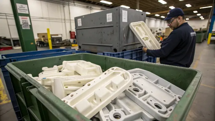
So, you’ve got a pile of warped parts. The big question on the buyer’s mind, and any business owner’s, is: can we salvage them? Can we make them usable? Honestly, it’s tough, and usually not a great long-term solution for businesses in comparable programs that produce precision components for consumer electronics where quality, consistency, and reliability are paramount. But let’s discuss the options:
- Post-Molding Cooling Fixtures: For some less critical parts, or parts made from certain materials, you mightbe able to clamp them into a cooling fixture immediately after molding. This fixture is shaped to the desired final geometry and is intended to hold the part in that correct shape as it finishes cooling and stabilizing. This can work sometimes, especially if the warpage isn’t too severe. However, it adds an extra step to your process, requires additional labor and equipment (the fixtures themselves), and might not be a permanent fix if the internal stresses locked into the part are too high – the part could still try to warp again later, especially under thermal cycling.
- Reheating and Reshaping (Annealing): Gently reheating the warped part (well below its full melting point, obviously, more like its heat deflection temperature) and then clamping it in a fixture or allowing it to cool slowly can sometimes relax some of the internal stresses causing the warpage. This is super tricky, highly material-dependent, and often leads to other issues like surface imperfections, further dimensional changes, or a reduction in mechanical properties. I generally advise against this for precision parts. It’s more of a last resort, “we’re desperate” kind of fix.
Really, the focus should generally, generally be on prevention. It’s far more cost-effective and reliable in the long run.Conformal Cooling.
This is where cooling channel design gets really sophisticated and, frankly, pretty cool. Instead of just straight-drilled holes that are limited by machining capabilities, conformal cooling channels are designed to follow the contours of the part, like a reliably tailored glove. Imagine cooling lines that snake around complex curves, maintain an optimal and consistent distance from the cavity surface everywhere, and can get right into those traditionally tricky-to-cool spots like sharp corners, deep ribs, or isolated cores.
How is this even possible? Often, it’s through metal additive manufacturing (also known as 3D printing of mold inserts or components). Technologies like Direct Metal Laser Sintering (DMLS) allow us to build mold inserts layer by layer, creating incredibly complex internal channel geometries that would be simply impossible with traditional drilling and milling.
The benefits for warpage reduction are HUGE:- Highly Uniform Mold Surface Temperature: This is the holy grail for minimizing warpage. By getting cooling precisely where it’s needed, in the right amounts, you can achieve a much more even temperature profile across the entire mold surface that contacts the plastic. This directly translates to more uniform cooling of the part as it solidifies, minimizing differential shrinkage and the resulting internal stresses.
- Reduced Cycle Times: Because cooling is so much more efficient and targeted with conformal channels, you can often significantly reduce the cooling portion of the injection molding cycle. And since cooling is typically the longest part of the cycle, even a few seconds saved per part adds up to massive productivity gains and cost savings in high-volume production. the buyer, with his focus on production efficiency and cost control, would definitely appreciate this aspect!
- Improved Overall Part Quality: Less warpage means better dimensional accuracy and consistency from part to part. It can also lead to better surface finish (fewer flow marks or gloss differences) and fewer internal stresses, which can improve the part’s mechanical performance and long-term stability.
Now, conformal cooling isn’t a universal solution for everysingle mold. It typically adds to the initial cost of the tool build because of the specialized design and manufacturing processes involved. So, you have to weigh that upfront investment against the long-term benefits. But for complex parts, parts with high aesthetic requirements, thin-walled applications, or high-volume parts where cycle time savings and reject reduction are absolutely critical, it’s an incredibly powerful tool. It’s the kind of technology that helps a manufacturing business stay competitive and reliable, especially in demanding sectors like consumer electronics. When I think about the challenges the buyer faces – ensuring reliable supply, managing lead times, maintaining top quality – investing in molds with well-designed conformal cooling can directly address these points by producing better parts, faster, and much more consistently. It’s a material change for many applications.Place Cooling Around the Thermal Problem
Channel distance, diameter, spacing and direction should respond to thick sections, ribs, bosses, slides and cosmetic surfaces. A uniform grid may leave a heavy boss hot or cool a thin edge too aggressively. Inserts and core features often need independent circuits or thermal bridges to avoid local hot spots.
Design for Flow Balance and Heat Transfer
Short, parallel circuits are easier to balance than one long serpentine path. Turbulent flow generally transfers heat more effectively than slow laminar flow, but the actual result depends on channel size, fluid properties, pressure drop and the temperature controller. Each circuit should be identifiable and measurable at the manifold.
Use Baffles, Bubblers or Conformal Features Carefully
Baffles and bubblers can cool deep cores where straight drilling is not practical. Conformal or near-surface channels may improve heat uniformity in complex inserts, but they require suitable manufacturing, sealing and inspection. The design should consider blockage, cleaning, leak risk and future repair.
Control the Mold Temperature, Not Just the Water Setpoint
The controller setpoint does not prove that the cavity surface has reached the intended temperature. Flow, pressure, hose routing, thermal oil or water properties, sensor location and startup time all matter. Temperature should be checked at the tool and monitored across circuits during trials.
Validate Cooling With Part Data
Compare cycle time, cavity temperature, part weight, dimensions, flatness and cooling-water temperature rise. If one cavity or region consistently differs, inspect flow balance and channel condition before changing packing. Cooling validation is strongest when it connects a thermal measurement to a dimensional result.
Injection Mold Cooling System Design: Buyer Review Checklist
- Map thick walls, bosses, ribs, inserts, slides and cosmetic surfaces before laying out circuits.
- Keep circuits short, identifiable and balanced with suitable flow and pressure reserve.
- Use baffles, bubblers or conformal inserts only with a maintenance and leak-control plan.
- Measure actual mold temperature and circuit flow rather than trusting the controller setpoint alone.
- Correlate cooling data with cycle time, flatness and critical dimensions during trials.
FAQ
How close should cooling channels be to the cavity?
The suitable distance depends on steel, channel size, wall thickness, surface requirements and structural limits; the goal is consistent heat removal without weakening the insert.
Is conformal cooling generally better?
No. It can improve difficult thermal zones, but cost, sealing, cleaning, inspection and repair must justify the complexity.
Conclusion
So, mastering your mold’s cooling system is absolutely key to beating warpage and producing top-quality parts. Focus on achieving uniform cooling through smart design, consider advanced options like conformal cooling for tricky parts, and generally prioritize prevention over cure. Your bottom line will thank you! 🔥