

Are you struggling to get plastic prototypes that truly match your final product’s intent? It’s frustrating when delays, material mismatches, and unexpected costs disrupt your development cycle. You risk falling behind schedule and blowing your budget on prototypes that don’t even work as intended. A solid grasp of CNC machining for plastics is the key to turning this around, ensuring your path from idea to production is smooth and efficient.
CNC machining can produce accurate plastic prototypes from engineering stock and is valuable when material identity, flatness, threads, sealing faces or tight interfaces matter. It does not automatically reproduce molded shrinkage, fiber orientation, weld lines or surface flow. The machining plan, stock material, fixturing, tool path, heat control and inspection method determine whether the prototype answers the intended question.
Related engineering resources: prototype injection molding | DFM analysis | mold design
To master CNC machining for plastic prototypes, focus on two core areas: material selection and design optimization. Choosing the right plastic based on its mechanical properties, thermal resistance, and cost is the first step. Next, optimize your CAD model for manufacturability (DFM) by simplifying geometry, maintaining uniform wall thickness, adding generous radii, and specifying appropriate tolerances. This dual approach ensures you get accurate, functional, and cost-effective prototypes quickly.
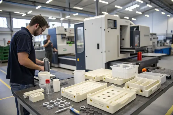
Which Plastic Is Best For Your CNC Machined Prototype?
Choosing a material from a long list of plastics feels like a shot in the dark, doesn’t it? You worry that picking the wrong one could mean your prototype fails during testing, looks cheap, or simply can’t withstand its intended environment. This uncertainty can lead to costly trial-and-error, wasting both time and resources you can’t afford to lose. The pressure to get it right the first time is immense.
The best plastic for your prototype depends entirely on your application’s requirements. For general-purpose, good-looking parts, use ABS. For high strength and transparency, pick Polycarbonate (PC). If you need excellent chemical and heat resistance, PEEK is the top choice, though it’s more expensive. For parts requiring durability and low friction, like gears or bearings, Nylon (PA) is ideal. Carefully evaluate mechanical strength, temperature needs, and appearance to make the right choice.
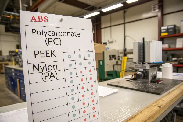
Understanding Key Material Properties
Before you can choose a material, you need to speak the language. Don’t worry, you don’t need a materials science degree. Just focus on a few key properties that matter most for prototypes:
- Tensile Strength: How much pulling force can it take before breaking? Essential for structural parts.
- Impact Resistance: Can it survive a drop or a sudden hit? Crucial for handheld devices and parts in high-traffic areas.
- Temperature Resistance: Will it melt, warp, or become brittle at its operating temperature?
- Cost: Raw material prices vary wildly. PEEK can be 10 times more expensive than ABS.
- Machinability: How easy is it for the CNC machine to cut? Softer plastics are faster to machine but may have a poor finish. Harder plastics give a great finish but take longer.
Common Plastics for CNC Prototyping
Here’s a quick-reference table to help guide your decision. I’ve included the plastics A common observation is used most often for a reason—they are versatile and reliable.
| Material | Key Features | Common Applications | Relative Cost |
|---|---|---|---|
| ABS | Good impact strength, easy to machine, great finish. | Consumer electronics casings, automotive trim, general-purpose prototypes. | Low |
| Polycarbonate (PC) | High impact strength, excellent transparency, good heat resistance. | Lenses, protective shields, medical devices, transparent covers. | Medium |
| Nylon (PA6/PA66) | Excellent wear resistance, low friction, high strength. | Gears, bearings, bushings, structural components. | Medium |
| Acrylic (PMMA) | High optical clarity, scratch-resistant, brittle. | Light pipes, display models, lenses, aesthetic parts. | Low |
| PEEK | Superior strength, extreme heat and chemical resistance. | Aerospace components, medical implants, high-performance parts. | Very High |
| Delrin® (POM) | High stiffness, low friction, excellent dimensional stability. | Bearings, gears, rollers, fuel system components. | Medium-High |
Think about your prototype’s primary function. Is it a “looks-like” model for a tradeshow? ABS or Acrylic might be suitable. Is it a “works-like” prototype for functional testing? You’ll need to look closer at PC, Nylon, or even PEEK if the application is demanding.
How Do You Optimize Your Part Design for CNC Machining?
You’ve spent weeks perfecting your design in CAD, but now you’re hearing from manufacturers that it’s “too expensive” or “impossible to make.” This is a common and incredibly frustrating roadblock. When a design isn’t optimized for manufacturing, you face high quotes, long lead times, and parts that don’t meet your specifications. You’re left feeling stuck, forced to choose between compromising your design or your budget.
To optimize your design for CNC machining, apply Design for Manufacturability (DFM) principles early. Focus on using uniform wall thickness, adding generous radii to all internal corners (at least 1/8th of the feature’s depth), and avoiding deep pockets. Eliminate undercuts whenever possible, or design them to be accessible. Finally, specify tolerances only where they are critical, as overly tight tolerances dramatically increase machining time and cost.
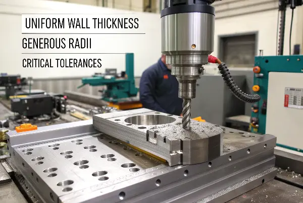
I can’t count the number of times a simple design tweak has saved a client thousands of dollars. One project that stands out involved a complex housing with several deep, square internal pockets. The initial quote was high because machining those sharp corners required specialized tooling and a lot of machine time. I sat down with the client and explained that if we increased the corner radii and slightly tapered the pocket walls, we could use a standard, more robust tool and run the machine much faster. They agreed to the changes, which didn’t affect the part’s function at all. The final cost was nearly 40% lower than the original quote. This is the power of DFM. It’s not about compromising your vision; it’s about working smarter with the manufacturing process.
Key DFM Principles for CNC
Think of these as the golden rules. Following them will make your parts easier, faster, and cheaper to produce.
- Add Corner Radii: CNC tools are round, so they can’t create reliably sharp internal corners. A good rule of thumb is to make your internal radii at least 1.5mm (0.06 in) or larger. The larger the radius, the larger the tool that can be used, which speeds up the process.
- Maintain Uniform Wall Thickness: Drastic changes in wall thickness can cause the plastic to warp or lead to sink marks. Try to keep walls a consistent thickness. If you can’t, make the transition gradual.
- Limit Pocket Depth: The deeper a pocket, the harder it is to machine. The tool has to be very long and thin, making it prone to vibration and breakage. As a general guide, try to keep the depth of any pocket to less than 4 times its width.
- Avoid Undercuts: These are features that can’t be machined from a single direction, as the material is “under” another feature. They require complex multi-axis machines or manual repositioning, both of which add significant cost.
A Practical DFM Checklist
Use this table to review your design before sending it out for a quote.
| Design Element | Best Practice (DO) | Common Mistake (DON’T) |
|---|---|---|
| Internal Corners | Add the largest possible radius. | Designing sharp, 90-degree internal corners. |
| Wall Thickness | Keep it uniform and between 1.5mm – 3mm. | Having very thick sections next to very thin walls. |
| Text & Lettering | Use engraved (debossed) text with a simple font. | Using raised (embossed) text, which requires machining away all surrounding material. |
| Tolerances | Specify tight tolerances only on critical features. | Applying a blanket tight tolerance to the entire part. |
| Holes | Design holes with standard drill bit sizes. | Specifying non-standard hole diameters that require custom tooling. |
Generally remember, the simplest design is often the best design. Before adding any feature, ask yourself: “Is this absolutely necessary for the part to function?” Every extra curve, pocket, and hole adds time and money to the project.
What Are The Most Common (And Costly) Mistakes To Avoid?
You’ve selected a material and optimized your design. You think you’re ready to go, but you still have a nagging feeling that you might be missing something. The fear of making a simple, overlooked mistake that ends up derailing your project is real. A small error in a CAD file or a miscommunication can lead to a batch of useless prototypes, setting you back weeks and blowing your budget.
The most costly mistakes in CNC plastic prototyping often stem from poor planning. The top three are: over-tolerancing the part, which needlessly increases machine time and cost; designing features that are impossible or impractical to machine, like sharp internal corners or deep, narrow pockets; and poor communication with your manufacturing partner, leading to incorrect assumptions about materials, finishes, or critical features.
Mistake 1: Over-Tolerancing
Tolerances define the acceptable variation for a specific dimension. While essential for mating parts, applying them unnecessarily is a huge cost driver.
- The Problem: Tighter tolerances require more precise machine setups, slower cutting speeds, and multiple inspection steps. A standard tolerance for CNC machining is around ±0.1mm (±0.004″). Tightening that to ±0.025mm (±0.001″) can easily double or triple the cost of the part.
- The Solution: Review your design and identify the truly critical dimensions. These are usually surfaces that mate with other parts, holes for pins or bearings, or features that affect the core function. Apply tight tolerances only to these features. For all other non-critical surfaces, use the manufacturer’s standard tolerance. Generally ask your machinist what their standard tolerance is.
Mistake 2: Ignoring Machinability
This goes back to DFM, but it’s a mistake so common it deserves its own section. Designers often create parts in the “suitable world” of CAD software without thinking about the physical reality of cutting tools.
- The Problem: Features like knife-edge thin walls (under 1mm), text on curved surfaces, or pockets too deep for a tool to reach will either be rejected by the manufacturer or result in a very high quote to cover the complex setup.
- The Solution: Think like a machinist. Visualize a spinning cutting tool moving across your part. Can it reach every surface? Are the walls thick enough to withstand the cutting forces without vibrating or breaking? Is there enough room for the tool to operate? If you are unsure, send your design to a potential supplier for a DFM review before you finalize it. Most good shops are happy to provide this feedback.
Mistake 3: Poor Communication
This is the silent killer of many projects. You assume the machinist knows what you want, and they assume your drawing is suitable.
- The Problem: Lack of clear notes on a drawing can lead to disaster. For example, if a surface needs to be reliably smooth for a seal, but you don’t specify the required surface finish, you might get a part with visible tool marks. If you don’t mark which side of the part is cosmetic, they might use that side for clamping, leaving marks.
- The Solution: Over-communicate. Use your 2D drawings to add notes. Clearly mark critical features, required surface finishes, and cosmetic surfaces. Provide a 3D STEP file for machining and a PDF drawing for reference and inspection. If you have a specific requirement, pick up the phone or write an email. A five-minute conversation can prevent a five-thousand-dollar mistake.
Select Stock That Represents the Decision
Choose a stock polymer with the required stiffness, temperature, chemical or friction behavior, and document how it differs from the production grade. Reinforced or filled stock may machine differently and may not reproduce molded orientation. For visual prototypes, color and surface may need a separate plan.
Design for Fixturing and Access
Provide datum surfaces, sacrificial tabs, workholding features and tool access. Thin walls, deep pockets and unsupported ribs can deflect or chatter. A good setup separates machining error from part flexibility and makes rechecking a feature possible.
Control Heat, Burrs and Stress
Cutting speed, feed, tool sharpness, coolant or air, chip evacuation and step-over affect melt, burrs, stress and surface. Some plastics soften or smear rather than cut cleanly. Allow the part to condition before final measurement when heat or residual stress matters.
Issue a CNC Prototype Quote Package That Can Be Inspected
Quoted accuracy is meaningful only when the material state, datum system, setup and measurement condition are defined. Replace blanket tolerances with a small set of functional features and ask the machinist to state any geometry that cannot be measured or held in the proposed setup.
| RFQ item | What to specify | What the supplier should return |
|---|---|---|
| Model and drawing | STEP revision, units, datum scheme, critical dimensions and reference-only dimensions | Revision acknowledgment and interpretation questions |
| Stock material | Polymer manufacturer/grade or required property, color, thickness and conditioning | Exact stock identity, substitution and certificate availability |
| Functional surfaces | Sealing, bearing, optical, cosmetic and assembly zones | Proposed setup, tool access, finish and protected surfaces |
| Inspection | Method, fixture/free state, temperature, conditioning and report format | Measured values, equipment and nonconformance disposition |
| Transfer to molding | Which tests the machined part must support | Documented limits for shrinkage, orientation, weld lines and molded stress |
Generic figures elsewhere in this article are design-screening examples, not guaranteed shop tolerances or universal minimum walls. Confirm capability for the exact plastic, geometry, feature depth, workholding and inspection method.
If the prototype is intended to release an injection-molded design, submit the CAD, drawing CTQs, stock grade and test plan through the CKMOLD RFQ so the machining evidence can be separated from later molding evidence.
Plan Tolerance and Surface by Function
Do not apply tight tolerances everywhere. Identify sealing, bearing, alignment, snap, fastener and cosmetic features, then match tool path and inspection to their function. A tight machined dimension may still fail when the production part shrinks or flexes differently.
Inspect and State Transfer Limits
Use datums, gauges, CMM or functional fixtures appropriate to the prototype. Record stock, orientation, setup, tool path and finishing. Carry the result into DFM with a note about which behaviors require molded samples or production-like testing.
CNC Machining for Plastic Prototypes: Buyer Review Checklist
- Choose stock for the material property the prototype must represent.
- Design datums, tabs, workholding and tool access before machining.
- Control heat, burrs, chip evacuation, deflection and residual stress.
- Apply tolerances and surface requirements only to functional or appearance-critical features.
- Inspect against a defined datum system and record transfer limits to molding.
Frequently Asked Questions
Is CNC machining more accurate than 3D printing?
It can provide tighter and more predictable dimensions for suitable geometries, but setup, tool access, material deflection and inspection still determine the result.
Can a CNC plastic prototype predict injection-molded dimensions?
It can validate interfaces and some material behavior, but molded shrinkage, fiber orientation, weld lines and cooling may require molded evidence.
Conclusion
Mastering CNC machining for your plastic prototypes isn’t about becoming a machinist yourself. It’s about understanding the key principles that drive success. By making informed material choices based on your application’s real-world needs and by optimizing your designs for manufacturability from the very beginning, you can dramatically reduce costs, shorten lead times, and get functional, high-quality prototypes every time. This knowledge transforms prototyping from a source of frustration into a powerful competitive advantage.