
Are your high-precision molded parts failing to meet tight tolerances due to unpredictable shrinkage? This leads to costly rework and delays. Discover CKMOLD’s meticulous approach to ensuring your parts are suitable.
High-precision molds need more than a shrinkage value copied from a resin sheet. They need a controlled workflow that connects product requirements, material selection, mold design, steel-safe planning, trial molding and dimensional feedback.
CKMOLD ensures precise shrinkage compensation by combining rigorous material testing, advanced simulation, and empirical data from actual molding trials. We calculate mold adjustments by analyzing material properties, part geometry, and specific processing conditions.
For the complete pre-tooling framework, use Injection Molding Shrinkage Risk Review Before Tooling. This page stays focused on compensation controls for precision tooling.
What is shrinkage and warpage?
Confused by parts that are not only the wrong size but also twisted out of shape? Shrinkage and warpage can turn your components into unusable scrap, impacting timelines and costs.
Shrinkage is the volumetric reduction a plastic part undergoes as it cools from melt temperature to ambient temperature. Warpage is the dimensional distortion or bending of a part, often caused by uneven shrinkage rates or internal stresses.
Dive deeper Paragraph: Shrinkage and warpage are two common headaches in injection molding. They are related, but not quite the same thing. Think of shrinkage as the material getting smaller overall. When molten plastic is injected into the mold, it’s hot and expanded. As it cools down to room temperature, the polymer chains pack closer together. The whole part reduces in volume. This is a natural, unavoidable physical process for almost all plastics. The amount it shrinks depends on the material type, additives, and processing conditions. Warpage, on the other hand, is when the part doesn’t just get smaller. It also twists, bends, or distorts from its intended shape. This usually happens because the shrinkage isn’t uniform across the part. Imagine one section of the part cooling and shrinking much faster than another. This difference creates internal stresses. If these stresses are strong enough, they will pull and push the part out of shape as it solidifies. So, while all parts shrink, not all parts warp. Warpage is essentially a symptom of differential shrinkage or poorly managed internal stresses. for the project team, designing a thin-walled electronic enclosure, understanding this difference is vital. Uniform shrinkage might be manageable by adjusting mold dimensions. But warpage can make the part completely unusable for assembly. Key factors influencing these are:
| Factor | Effect on Shrinkage | Effect on Warpage |
|---|---|---|
| Material Type | Varies (e.g., crystalline > amorphous) | Can increase if non-uniform |
| Wall Thickness | Thicker sections may shrink more | Differential shrinkage if varied |
| Mold Temperature | Higher temp can increase post-shrinkage | Uneven cooling leads to warpage |
| Packing Pressure | Higher pressure reduces shrinkage | Can induce stress if not uniform |
| Fiber Orientation | Anisotropic (directional) shrinkage | Can cause significant warpage |
| Gate Location | Affects flow and packing distribution | Poor location can increase stress/warpage |
At CKMOLD, we focus on predicting both to ensure dimensional stability and part integrity from the outset.
How to calculate shrinkage in mold?
Do your mold designs consistently miss the mark, resulting in undersized parts? Relying on generic datasheet values for shrinkage can lead to expensive mold rework and production delays.
To calculate shrinkage for a mold, use the formula: Mold Dimension = Part Dimension / (1 – Shrinkage Rate). The shrinkage rate is determined from material datasheets, empirical testing, or simulation, expressed as a decimal (e.g., 0.005 for 0.5%).
Dive deeper Paragraph:
Calculating the right amount of shrinkage compensation for a mold is more than just plugging a number into a formula. It is a science and an art. The basic idea is straightforward. If you know your plastic part needs to be a certain size, and you know the plastic will shrink by a certain percentage, you need to make the mold cavity bigger by that percentage. The formula we start with is Mold Dimension = Desired Part Dimension / (1 - Shrinkage Rate).
So, if the project stakeholder needs a part to be 100mm long, and the material’s shrinkage rate (S) is 0.5% (or 0.005 as a decimal), the mold dimension (Dm) would be D<sub>m</sub> = 100mm / (1 - 0.005) = 100mm / 0.995 ≈ 100.5025mm.
But here’s where it gets tricky. That “Shrinkage Rate” isn’t a single, fixed number. It’s influenced by many things:
- Material Type: Amorphous materials like ABS or PC generally shrink less and more uniformly than semi-crystalline materials like PP or Nylon. Semi-crystalline materials have more complex shrinkage due to their ordered molecular structure.
- Additives: Fillers like glass fibers or talc typically reduce shrinkage. They add bulk that doesn’t shrink as much as the base polymer.
- Processing Conditions: Melt temperature, mold temperature, injection pressure, packing pressure, and cooling time all play significant roles.
- Part Geometry: Wall thickness is a big one. Thicker sections cool slower and can shrink differently, and often more, than thin sections.
- Flow Direction:For fiber-filled materials, shrinkage is often less in the direction of material flow and more in the direction transverse (perpendicular) to flow. This anisotropy is crucial to consider. At CKMOLD, we start with material datasheet values. But we generally cross-reference with our extensive historical data from similar parts and materials. For truly high-precision molds, we often recommend running mold flow simulations. This software can predict how the plastic will flow, cool, and shrink. It takes into account the specific part geometry and processing parameters. We might even mold test plaques or a prototype cavity to get empirical shrinkage data for the exact material batch and conditions. It is an iterative process. The initial datasheet shrinkage was a range. We narrowed it down with simulation and then fine-tuned it after the first trial shots. This meticulous approach saved a lot of steel adjustments and time.
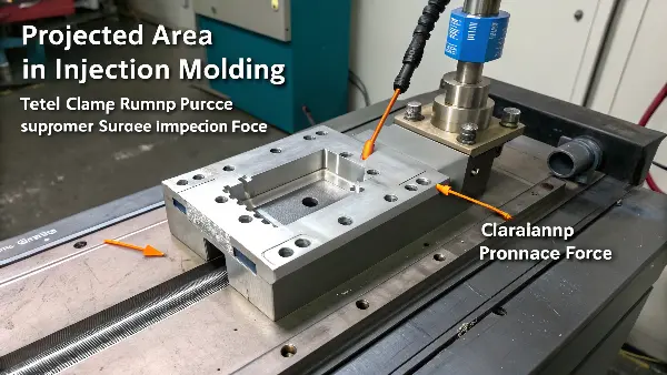
What is the projected area in injection molding?
Unsure how much clamping force your mold truly needs? Underestimating clamping force leads to flash and part defects. Overestimating wastes energy and can damage the mold or machine.
The projected area in injection molding is the total surface area of the part, including runners, as viewed from the direction of the clamp force (perpendicular to the parting line). It’s used to calculate the minimum required clamping force.
What is the formula for injection pressure?
Guessing injection pressures and getting inconsistent part quality? Incorrect injection pressure leads to short shots, flash, or high internal stresses. All these impact part dimensions and shrinkage.
There isn’t one simple formula for injection pressure; it’s determined by material viscosity, flow length, wall thickness, gate size, and melt/mold temperatures. It’s typically set empirically and optimized during process development.
Dive deeper Paragraph:
Unlike a neat mathematical equation for something like clamping force, there isn’t a single, universal “formula” to calculate the exact ideal injection pressure before you start molding. It’s more of a target. This target is found through a combination of experience, material data, simulation, and systematic process optimization on the machine.
Injection pressure is the force exerted by the screw or ram to push the molten plastic into the mold cavity. It needs to be high enough to overcome all the resistances the plastic encounters during its journey. These resistances include:
- Material Viscosity: Thicker, more viscous materials (like high molecular weight polymers or heavily filled compounds) need higher pressure to flow.
- Flow Path Length & Thickness: Longer flow paths and thinner wall sections create more resistance, requiring more pressure. Think of trying to push honey through a long, thin straw versus a short, wide one.
- Gate Size & Type: Smaller gates restrict flow and necessitate higher pressure to fill the part adequately.
- Melt & Mold Temperatures: Colder melt or a colder mold increases the plastic’s viscosity, thus needing higher injection pressure.
- Venting: Poor mold venting can trap air. This trapped air creates back pressure that the injection pressure must overcome.
While there’s no direct calculation formula for the pressure setting itself, machine software and advanced mold flow simulations can predict required pressures based on these inputs. In practice, injection pressure is typically set and controlled in two main stages on the molding machine:- Filling Phase Pressure (Boost Pressure): This is the initial high pressure used to fill the cavity quickly (e.g., 95-99% full) before the plastic freezes off at the gate or thin sections.
- Packing/Holding Phase Pressure: Applied after the cavity is mostly full, this pressure (often lower than boost) packs additional material into the cavity. This compensates for shrinkage as the plastic cools and solidifies. This phase is crucial for minimizing voids, sink marks, and directly impacts the final part dimensions and the effectiveness of shrinkage compensation.
for the project team, understanding these phases is key. If the packing pressure is too low, the part will show more shrinkage and potential sink marks. If it’s too high, it can lead to flash, overpacking (which can cause parts to stick or have high internal stresses), or even damage the mold. We at CKMOLD typically start with material supplier recommendations. Then, we meticulously fine-tune the pressures on the machine, carefully monitoring part weight, critical dimensions, and visual quality. I generally tell the production team, “Listen to the plastic, watch the process.” The machine’s pressure readings and the resulting parts tell you a detailed story about what’s happening inside the mold.For related manufacturing support, review CKMOLD injection mold services, mold design, DFM analysis, mold testing and validation, and production injection molding.
DFM Review Before Steel Cutting
CKMOLD reviews wall thickness, ribs, bosses, gate position, tolerance stack-up and assembly requirements before finalizing cavity dimensions. This early review helps identify dimensions that are vulnerable to anisotropic shrinkage, local sink or warpage. It also gives the customer a chance to adjust product geometry before the mold becomes expensive to change.
Material and Process Assumption Control
The team confirms resin grade, filler content, expected mold temperature and likely production machine range. If the customer has not finalized the resin, CKMOLD highlights the risk and may recommend steel-safe design on critical areas instead of pretending that a temporary material assumption is final.
Steel-Safe Design and Mold Trial Feedback
For selected dimensions, CKMOLD can leave controlled steel allowance so corrections after T0 or T1 are precise. Trial reports then compare measured part data against the original assumptions. This feedback loop improves both the current mold and future projects using similar materials or geometries.
Why This Matters for Export Tooling
Export molds must run correctly after shipment, often without CKMOLD technicians standing beside the press. A documented shrinkage-compensation process makes remote support easier because the customer can see why dimensions were chosen and how trial corrections were decided.
Buyer and Engineering Checklist
- Confirm critical-to-function dimensions during DFM, not after T0.
- Use material-grade-specific shrinkage data whenever possible.
- Protect uncertain dimensions with steel-safe planning.
- Measure T0 and T1 samples with the same inspection method.
- Keep shrinkage assumptions in the mold handover documentation.
FAQ
How does CKMOLD reduce shrinkage risk before mold trial?
CKMOLD combines DFM, material review, mold-design experience and steel-safe planning so the first trial starts from a controlled assumption.
Can CKMOLD support shrinkage issues after export mold delivery?
Yes. Clear trial data, process records and mold documentation make remote troubleshooting and correction planning much more effective.
Conclusion
CKMOLD’s precision in shrinkage compensation stems from a deep understanding of material behavior and meticulous calculation. We adapt to real-world process variables, ensuring high-quality, dimensionally accurate parts every time.