
A shrinkage calculation is only an assumption until measured parts prove it. Validation turns the project from guesswork into evidence. The strongest validation reports connect part dimensions, process settings, material condition and mold trial observations in one record.
To validate shrinkage calculations, meticulously measure critical dimensions on both the mold and the cooled, stabilized parts using precision instruments. Then, compare these actual measurements against your theoretical shrinkage values to refine your design and process.
For the complete pre-tooling framework, use Injection Molding Shrinkage Risk Review Before Tooling. This page stays focused on T1 measurement, conditioning and validation.
How to calculate part shrinkage accurately?
Calculating part shrinkage involves precisely measuring a specific dimension on the cold mold and the corresponding dimension on the fully cooled and conditioned part, then applying these values to a standard shrinkage formula.
Step-by-Step Guide to Calculation
- Identify Critical Dimensions: First, pinpoint the features on your part where dimensional accuracy is most crucial. These are the dimensions you’ll focus on. For the project team, this might be mating surfaces or snap-fit features.
- Measure Mold Cavity/Core Dimension (Cold): Before any production, accurately measure the relevant dimension on the actual steel of the mold cavity or core at room temperature. Don’t rely solely on the mold’s design drawing, as manufacturing tolerances can exist. Use calibrated instruments.
- Mold Parts Under Stable Conditions: Run the injection molding process until it’s stable and producing consistent parts. Ensure all process parameters (temperatures, pressures, times) are set and maintained.
- Control the measurement state: Agree the time after molding, temperature, humidity and conditioning method. ASTM D955’s public scope includes 24- and 48-hour observations for thermoplastic specimens; these are timed measurements, not proof of equilibrium for every production part.
- Measure the corresponding part feature: Record individual values, cavity and shot sequence with the agreed gauge and fixture. Select sample quantity from the diagnostic or qualification objective; keep the mean and spread separate.
-
Apply the shrinkage formula: Shrinkage Rate (%) = [(Mold Dimension – Average Part Dimension) / Mold Dimension] × 100. A dimensional offset should prompt checks of the measurement method, conditioning, material and process before a steel correction is approved.
How do you calculate actual shrinkage using the formula?
Actual shrinkage is calculated with the formula: Shrinkage (%) = [(Dimension of Mold – Dimension of Part) / Dimension of Mold] x 100. This expresses the reduction in size as a percentage of the original mold dimension.
The formula itself looks straightforward, but the integrity of the data you plug into it is everything.
Understanding the Shrinkage Formula Components
- Dimension of Mold (Dm): This is the specific dimension measured directly on the mold cavity (for an external part feature) or mold core (for an internal part feature) at a standard temperature (e.g., room temperature before the mold heats up in production). This is your baseline, the size you intended the plastic to conform to when molten.
-
Dimension of Part (Dp): This is the corresponding dimension measured on the actual injection-molded part after it has been ejected, cooled and conditioned for the agreed measurement interval. A 24- or 48-hour reading is a timed observation, not proof of equilibrium for every material.
The formula,
Shrinkage (%) = [(D_m - D_p) / D_m] × 100, essentially tells you how much smaller the part became relative to the mold size that formed it.Illustrative calculation: Assume a measured mold cavity length (Dm) of 150.00 mm and a mean part length (Dp) of 149.10 mm at an agreed 24-hour observation. These are assumed numbers, not a CKMOLD project result:
Shrinkage (%) = [(150.00 mm – 149.10 mm) / 150.00 mm] × 100
Shrinkage (%) = [0.90 mm / 150.00 mm] × 100Shrinkage (%) = 0.006 × 100 = 0.6%
The assumed readings give 0.6% for this feature and measurement state. They do not establish a universal shrinkage factor or justify scaling every axis by the same amount. Repeat the assessment for relevant directions and features, and evaluate measurement uncertainty before approving a small steel correction.
How do you measure shrinkage effectively?
Effective shrinkage measurement relies on using calibrated, high-precision instruments like digital calipers, micrometers, or CMMs, and consistently applying them to defined features on both the mold and conditioned parts under controlled environmental conditions.
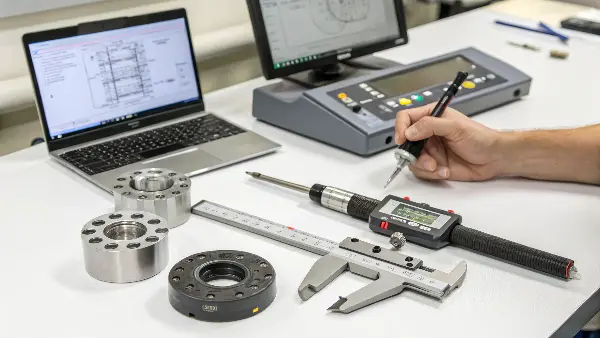
Essential Tools and Techniques
-
Choosing the Right Instrument:
- Digital calipers: Suitable for accessible features when contact force, alignment and uncertainty meet the measurement requirement. Display resolution alone does not establish accuracy.
- Micrometers: Useful for suitable thickness or diameter features with controlled contact force and alignment. Check whether the part deforms under measurement.
- Coordinate measuring machines (CMMs): Useful for defined datum systems and complex features; validate the fixture, probing strategy and uncertainty for the actual plastic part.
- Optical Comparators/Vision Systems: Useful for measuring profiles, radii, angles, and small features that are hard to access with contact instruments.
- Calibration and method control: Use instruments with suitable traceable calibration and verify the complete measurement method, including fixture and operator effects.
- Consistent Measurement Points: Define exactly where on the mold and part you will take measurements. Use datums or clearly marked reference points. Ensure you measure the same feature in the same way every time.
- Define the measurement age, temperature, humidity and material state in the agreed test plan. ASTM D955 includes 24- and 48-hour observations for its specimens; these times do not prove moisture equilibrium or in-use stability for every nylon or production part.
- Measure multiple samples: Track results by cavity and shot sequence under a documented process state. A small diagnostic set can reveal a problem but does not establish production capability by itself.
-
Document the date, time, operator, instrument, calibration status, ambient conditions and each measurement. Record the time since molding and conditioning method so results from different operators can be compared on the same basis.
Scope Boundary: Vulcanized Rubber
NBR requires a separate compound, cure/post-cure and dimensional validation plan. Do not transfer a thermoplastic shrinkage factor or treat ASTM D955 as qualification of a vulcanized rubber component. Obtain the exact compound supplier’s data and verify the specified finished-part condition.
Define the Measurement Plan Before Trial
Do not wait until parts are molded to decide what matters. The team should mark critical-to-function dimensions, cosmetic reference dimensions and likely warpage zones before T0. This makes trial measurement faster and prevents the team from overlooking the dimensions that actually control assembly.
Control Cooling and Conditioning Time
Many plastics continue changing size after ejection. Semi-crystalline and moisture-sensitive materials can be especially sensitive. Validation should state whether dimensions were measured immediately, after 24 hours, after conditioning or after a customer-specified stabilization period.
Compare Dimensions Against Process Data
Every measured sample should be tied to process conditions such as melt temperature, mold temperature, packing pressure, packing time, cycle time and part weight. This makes it possible to distinguish real steel-size error from process-driven variation.
Use Validation to Guide the Next Action
A consistent offset is a reason to investigate steel only after measurement, conditioning, material and process causes have been checked. If the data shows inconsistent movement, the team should stabilize the process, review cooling or inspect measurement repeatability before changing steel.
Buyer and Engineering Checklist
- Create a measurement map before the first mold trial.
- Measure several cavities separately on multi-cavity molds.
- Record the time between molding and inspection.
- Attach process parameters to every sample set.
- Approve steel correction only after the variation source is understood.
FAQ
How many parts should be measured during shrinkage validation?
It depends on cavity count and tolerance risk, but one part is not enough. Measure enough samples to separate random variation from a repeatable trend.
Why should cavity numbers be tracked?
Cavity tracking shows whether the issue is global shrinkage, a single cavity problem, or a balance issue in a multi-cavity tool.
A Measurement Record That Can Support a Tool-Correction Decision
Report the measured steel dimension and each corresponding part result, not only nominal CAD size and an average. Include cavity, shot sequence, drawing revision, gauge/fixture, operator, material lot, process state and time since molding. Keep per-cavity means and spread separate.
Gauge resolution is not measurement uncertainty. A thin or flexible part may deflect under contact force or change when clamped to a datum fixture. Repeat suspect results with an agreed method before interpreting a small difference as material shrinkage.
Label a 5–10-part set as an initial diagnostic sample unless a justified sampling plan says otherwise; it does not by itself establish production capability. Record nonconforming results as well as acceptable ones. Submit the dimensional report and process record through the project enquiry form when requesting a correction review.
Technical reference: NIST’s measurement-uncertainty guidance. The post-T1 steel-correction decision guide addresses the related decision separately.
Conclusion
Use the trial record to separate measurement, material, conditioning and process effects before changing steel. Retain the measured dimensions, cavity-specific variation and agreed acceptance limits so the next trial can verify whether the correction addressed the cause.