
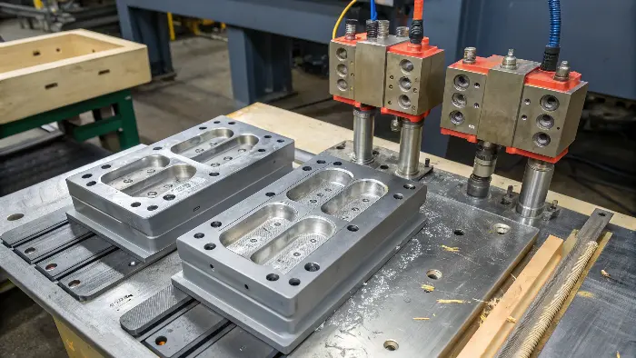
Quick answer: The machine supplies clamp, melt preparation, injection, motion and controls; the mold creates part geometry, distributes melt, removes heat, vents gas and releases the part. Production succeeds only when their mechanical, thermal, electrical and process interfaces are designed and validated together.
Selection Matrix
| Responsibility | Molding machine | Injection mold |
|---|---|---|
| Shape | Positions and clamps the tool | Core, cavity, inserts and actions form geometry |
| Material | Melts, meters and injects resin | Runner and gates distribute it to cavities |
| Thermal | Provides controllers and coolant support | Circuits and steel remove heat from the part |
| Release | Opens, drives ejector and coordinates robot | Draft, actions and ejection support the part |
What the Machine Controls
The injection unit feeds pellets, melts and meters the shot, drives a velocity profile and supplies packing pressure. The clamp unit closes the mold, resists cavity pressure, opens to a defined position and drives or coordinates ejection. The controller sequences these events and records signals.
Machine capability includes more than tonnage: screw size, shot utilization, injection pressure and rate, plasticizing, platen, daylight, nozzle, ejector, actions and I/O all matter.
What the Mold Controls
Core and cavity define shape and surface. Sprue, runner, hot runner and gates control flow, balance and vestige. Vents release air. Cooling circuits establish the thermal pattern. Parting, interlocks and support resist load, while slides or lifters release undercuts.
The mold also determines maintenance burden and many dimensional correction options. It is a production machine in its own right, not a passive metal box.
Mechanical Interfaces
Mold envelope must fit tie bars, platen, mold thickness, opening and loading access. Locating ring, nozzle radius, sprue, clamps, support and ejector must align. Actions need stroke, force, connectors and safe home confirmation.
Nominal clamp tonnage does not prove compatibility. Use machine drawings and a mold-interface sheet before build, test or transfer.
Selection Evidence Checklist
- Separate machine, mold, material and product responsibilities.
- Verify platen, tie bars, daylight, thickness, nozzle and ejector.
- Match shot, screw, pressure, rate, recovery and clamp demand.
- Map cooling, heat, air, hydraulic and electrical interfaces.
- Coordinate actions, sensors, ejector, robot and mold protection.
- Develop the process on the specific controlled configuration.
- Define ownership, spares, drawings and maintenance records.
- Classify trial issues from evidence across all systems.
Thermal and Utility Interfaces
Machine-side equipment supplies coolant, heat, air, hydraulic power and hot-runner control; mold circuits and components convert those utilities into a cavity condition. Flow, pressure, temperature, media, hose and electrical zones should be mapped and labeled.
A correct setpoint cannot overcome a blocked channel, reversed hose or inadequate pump. Verify actual flow and representative mold-surface temperature during validation.
Process and Control Interfaces
Machine velocity generates flow through the mold; pressure rises in response to material and restriction. Transfer, packing and gate freeze connect machine settings with mold geometry. Sensors can provide cavity or action evidence, but their definitions and limits must be validated.
Robot, ejector, slides and mold protection need a safe sequence. The process window belongs to the specific machine–mold–material configuration unless transfer evidence proves equivalence.
Ownership Through the Program
The tooling specification should define mold ownership, target and backup machines, interfaces, controllers, drawings, spares and maintenance. The molder owns safe operation and the approved process; the product owner approves requirements and changes according to the project agreement.
At T1, verify both sides together. A defect may originate from product, mold, machine, material, process or handling, so corrective action should follow evidence rather than contractual assumptions.
Illustrative Interface Failure
Illustrative engineering example—not a claimed CKMOLD customer result: A mold fits the platen and clamp rating, yet recovery time exceeds cooling because the receiving machine has a smaller screw. The part can be made, but target cycle and material residence are not demonstrated. Compatibility is corrected by qualifying a different press, not by declaring the mold defective.
Continue the Selection Review
Selection Questions
Is an injection mold part of the injection molding machine?
It is separate tooling installed in the press, but the two operate as one production cell through defined interfaces.
Who creates the part shape?
The mold’s core, cavity, inserts and moving features create geometry; the machine supplies material, pressure, clamp and motion.
Can one mold run on several machines?
Yes when physical, injection, clamp, utility and control compatibility are verified and the process is qualified.
Which system causes an injection molding defect?
Defects can arise from product design, mold, machine, material, process or handling. Diagnosis should classify evidence before correction.
Apply the Injection Mold vs. Injection Molding Machine review to your released design. Share the function, exact resin, annual volume, CTQs, cosmetic limits and launch timing through the CKMOLD project form. If CAD is relevant, send it directly to jerry@ckmold.com; the form does not require an upload.