
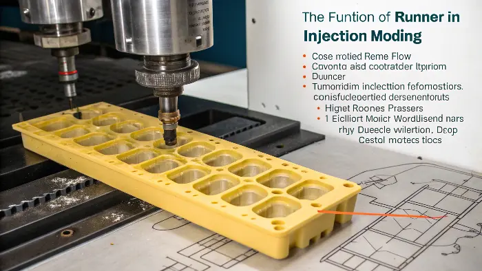
A runner is the melt-distribution channel between the sprue or hot-runner inlet and the gate. Its design affects pressure loss, balance, material history, scrap and the evidence needed to approve a multi-cavity process.
A runner is the channel that carries molten plastic from the sprue or hot-runner manifold toward one or more gates in an injection mold. Its cross-section, length, layout, transition and temperature influence pressure loss, filling balance, material waste, cycle time and part quality. Runner design is therefore a flow-system decision, not simply a passage that connects the machine nozzle to the cavity.
Related CKMOLD resources: mold design, multi-cavity injection molds, production injection molding.

What Is a Runner System?
A runner carries melt between the sprue or hot-runner inlet and the gate. The gate is the restricted transition into the cavity; it is not simply another name for the runner. The system must deliver melt with acceptable pressure loss, temperature history, shear and balance while supporting separation, maintenance and scrap goals.
A cold runner solidifies and is ejected with the part or separately. A hot runner keeps melt in a heated manifold/nozzle system. “Naturally balanced” describes equal geometric flow paths; it does not guarantee equal cavity filling when cavity, gate, cooling or material conditions differ. For a higher-risk layout, use mold flow analysis to compare documented alternatives, then validate the selected system at T1.
Primary sources checked: Autodesk — Runner System (runner layout and balanced filling context); Autodesk — Gate Location (gate position and filling-result context). The cited scope still has to be matched to the exact grade, tool, product and destination market.

How Are Runner Layouts and Cross-Sections Described?
- Single- or multi-branch layouts: route melt to one or many cavities; branch lengths and diameters affect balance.
- Naturally balanced layouts: use equivalent paths, but still require validation for gate/cavity differences.
- Artificially balanced layouts: tune diameters or restrictions to compensate for unequal paths.
- Round, trapezoidal or modified cross-sections: trade pressure loss, machining, parting-line location and extraction.
- Tapered sprues and transitions: assist release and reduce abrupt flow changes.
Fan, tab, disk, pin and edge are gate descriptions, not runner-layout categories. Keep the terminology distinct on the tool drawing and simulation report.
What Is the Difference Between Sprue, Runner and Gate?
The sprue receives melt from the machine nozzle in a conventional cold-runner mold. The runner distributes it toward one or more cavities. The gate meters the final entry into the cavity and influences filling pattern, shear, pressure transfer, freeze-off and vestige.
Specify cross-section and size from material rheology, shot size, flow length, cycle, regrind policy and pressure capacity. A full-round runner often provides favorable flow area, but it requires machining in both mold halves and is not automatically the best choice.

How Should the Gate and Runner Be Designed Together?
Gate location determines how the cavity fills; runner layout determines how melt reaches that gate. Review them together with weld-line position, air traps, appearance, fiber orientation, pressure drop, clamp demand and packing. Gate freeze must also support the required packing strategy.
For multi-cavity tools, compare cavity-by-cavity fill time, pressure, temperature and part weight during T1. If cavities differ, investigate gates, runners, vents, cooling and cavity geometry before simply changing machine settings.

What Evidence Should a Buyer Review?
- tool drawing with sprue, runner and gate dimensions;
- material and rheology inputs used for sizing or simulation;
- predicted or measured pressure demand and fill balance;
- cold-runner mass or hot-runner specification and maintenance plan;
- gate vestige and allowable appearance zones;
- cavity-to-cavity part-weight and dimensional data at approval.
What Must the Runner Accomplish?
The runner must deliver a stable melt to every gate without excessive pressure loss, shear heating, residence time, imbalance or material waste. Its success is measured in molded evidence: fill pattern, cavity balance, part weight, dimensions, appearance and a stable process window—not by geometry alone.

Cold Runner and Hot Runner Systems
A cold runner solidifies with the molded parts and normally becomes regrind or waste unless it is separated and reused. A hot runner keeps the flow path heated so the runner can remain molten and the mold can reduce runner scrap. Hot runners add cost, temperature-control requirements, maintenance points and start-up considerations.
Runner Layout and Cavity Balance
A balanced layout gives cavities similar flow lengths and resistance, but geometric balance alone does not support filling balance when parts, gates or cooling conditions differ. Family molds require special attention because the largest or most restrictive part can control the process. Simulation and short-shot trials can reveal imbalance.
Cross-Section and Pressure Loss
A runner that is too small can create excessive shear, pressure loss, early freeze-off and difficult filling. A runner that is oversized may increase material volume, cooling time and scrap. Smooth transitions, appropriate radii and a design matched to resin, wall thickness and shot size are more important than copying a generic dimension.
Runner-to-Gate Transition
The runner should deliver a stable flow into the gate without creating sharp dead zones, excessive shear or jetting. Gate type and location determine how the runner feeds, packs and separates from the part. The transition also affects weld lines, fiber orientation, gate vestige and cosmetic risk.
Maintenance and Troubleshooting
Runner problems can appear as cavity-to-cavity weight variation, short shots, flash, burn marks, stringing, drool, color streaks or long cycle time. Check hot-runner temperatures, nozzle alignment, blockage, wear, venting, resin changeover and cold-slug design before changing pressure alone.
Runner-System Buyer Review Checklist
- Are sprue, runner and gate terms used consistently on drawings?
- Are sizing assumptions tied to the exact resin and expected process?
- How will cavity balance and gate freeze be verified at T1?
- What runner scrap, regrind or hot-runner maintenance is included?
- What gate vestige, weld-line and appearance limits apply?
FAQ
What is the purpose of a runner?
A runner carries molten plastic from the sprue or hot-runner system to the gate or gates that feed the mold cavity.
Is a hot runner generally better?
No. Hot runners can reduce runner scrap and support high-volume production, but they add cost, temperature-control requirements and maintenance complexity.
Conclusion
A runner is the melt-distribution path between inlet and gate. Choose its layout and cross-section with the gate, resin, cavity arrangement and machine limits, then approve it from cavity-level fill and quality evidence.