
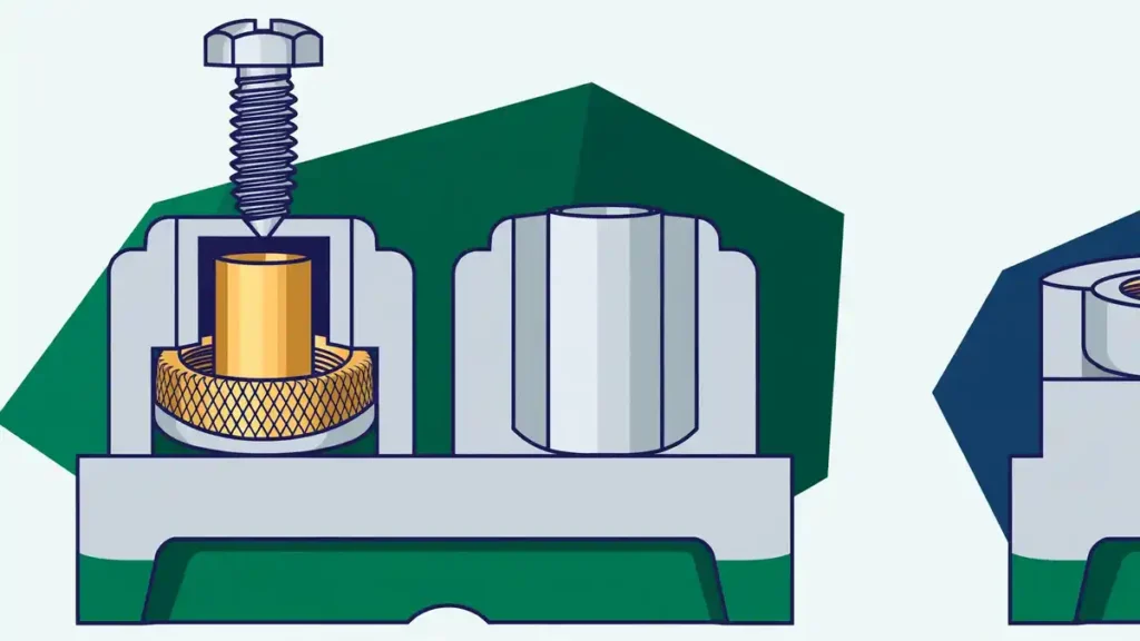
A serviceable housing comes back from the field with a stripped screw hole — the cover was opened a dozen times for battery changes, and on the thirteenth the screw turns freely in chewed-up plastic. Both failures have the same root: the thread was treated as a detail, decided late, on a drawing that never named the insert, the hole, or the boss.
Choose the insert by three things, in this order: how many times the joint will be opened, whether the resin is a thermoplastic or a thermoset, and how many parts you make a year. Then size the boss from the insert’s outside diameter — PennEngineering’s rule is a boss outside diameter at least twice the insert diameter — and check the molded hole against the insert maker’s tolerance, because a hole oversized by 0.005 in (0.13 mm) can cut pull-out strength by 30–40%. Get those decisions right and a threaded insert gives you a reusable metal thread in a plastic part for the life of the product.
This guide works from the decision outward: when an insert beats a self-tapping screw, which of the four installation methods fits your part, what the insert should be made of, a worked check you can run on an M4 boss, the five boss-design rules that prevent the common failures, and what to put in an RFQ so a supplier quotes the insert rather than guessing at it.
When does a part need a threaded insert at all?
A self-tapping screw cut directly into a molded boss is cheap and simple, and for a joint that is assembled once and never opened again, it is often the right answer. The problem starts with repetition. Every time a self-tapping screw is driven in and out, it re-cuts the plastic thread a little further, and the thread loses grip. One published buyer’s guide puts the line at 5 to 10 openings: beyond that, for battery service, calibration, or field maintenance, direct screws eventually strip the polymer threads. A metal threaded insert solves it by moving the wear surface from plastic to metal — the screw turns in a brass or stainless thread, and the insert itself is anchored into the boss by knurls that spread the load over a much larger surface.
The second reason is clamp load. A machine screw in a metal insert can be torqued to a real preload, which matters where a cover must stay sealed against a gasket or a structural joint must not work loose under vibration. A self-tapping screw in plastic cannot carry the same preload without creeping or stripping, and the torque you can apply is limited by the plastic, not the screw. If the joint carries high clamp preload, or must survive repeated assembly, an insert is the answer. If neither applies — one assembly, light load, a cover that never comes off — a self-tapping screw saves the insert cost and the secondary operation, and the honest recommendation is to skip the insert.
There is one more case worth naming: a part that must be assembled and disassembled during manufacturing itself, for example a housing that is opened for testing and then closed for shipment. Even a handful of cycles during production can strip a direct screw thread before the customer ever touches the product. Count the cycles across the whole life of the part, not just in the customer’s hands.
The four ways to put an insert into a plastic part
PennEngineering, the maker of the SI range of threaded inserts for plastics, describes four primary installation methods. They differ in when the insert goes in — during molding or after — and that one difference drives strength, cost, and tooling.
| Method | How it works | Relative strength | Cycle / tooling impact | Best fit |
|---|---|---|---|---|
| Heat-set (thermal press) | A heated tip melts a thin film of plastic around the insert as it is pressed into a pre-formed hole | High — one published comparison puts it at 85–95% of molded-in | 3–6 s per insert off-line; several can be gang-pressed at once; no mold complexity | Prototypes through medium production (roughly 100–100,000 parts a year); thin-wall PC and ABS housings |
| Ultrasonic | A horn vibrating at 20–40 kHz melts the plastic by friction as the insert is pressed in | High — 80–90% of molded-in in the same comparison | 0.5–1.2 s per insert; needs a tuned horn fixture and tight hole control | Medium-to-high volume (roughly 25,000–500,000 a year) where heat-setting is too slow |
| Molded-in | The insert is placed on a core pin in the mold and the resin flows around it during the shot | Highest — the baseline the others are measured against | Slows the press cycle by 4–15 s unless robot-loaded; a dropped insert can damage cavity steel | High-load structural mounts (M5–M10), thermosets, or dedicated high-volume lines |
| Cold press-in (expansion) | The insert is forced into an unheated hole; slotted expansion types flex inward, then bite outward when the screw is driven in | Lowest — roughly 40–60% of molded-in; relies on friction and hoop interference | Fastest and cheapest; a simple arbor press is enough | Non-critical covers in ductile PP, PE, or nylon where the load stays light |
A fifth option exists for thick-walled parts: self-tapping or thread-cutting inserts, which cut their own thread into a molded hole as they are screwed in. They approach molded-in strength in thick glass-filled nylon, PBT, or structural foam, but they need a much thicker boss wall — at least 2.2 times the insert outside diameter — so they are a special case, not a default.
Molded-in inserts are one use of insert molding as a process. Where the question is which multi-material route fits the whole part — not just the thread — the insert, overmold and two-shot decision guide compares all three routes, including the TPE compatibility and volume break-even that decide between them.
Two rules cut through the table. First, heat-set and ultrasonic installation both re-melt the plastic, so they only work on thermoplastics. For a thermoset part the choice is molded-in or cold press-in, and the elasticity of the resin becomes the deciding factor for press-in. Second, molded-in gives the best bond because the molten resin flows under pressure into deep knurl undercuts — but it is the only method that touches the mold itself, adding core pins, cycle time, and the risk of an insert dropping into the cavity. That is why the same buyer’s guide puts the cost crossover where it does: post-molded heat-set or ultrasonic inserts are more economical below roughly 25,000–50,000 parts a year, while molded-in wins above about 100,000 a year on a dedicated line with automated loading. Between those volumes, the decision is about the joint’s load and the mold’s complexity, not the insert price alone.
The practical difference between heat-set and ultrasonic deserves a closer look, because on paper they look interchangeable — both give nearly the same pull-out and torque-out strength, within 5–10% of each other. The difference is in what they do to the boss. Heat-setting melts a uniform film around the knurls with controlled conductive heat, which leaves the lowest residual hoop stress in the boss and the most consistent retention in notch-sensitive resins like polycarbonate. Ultrasonic is faster, but it needs precise control: too much amplitude or a poorly tuned horn can cold-force the insert or crack a thin boss, and it can leave a larger process-affected zone. If the part is a thin-wall polycarbonate housing and the volume does not demand ultrasonic speed, heat-set is the safer default. If the line runs hundreds of thousands of parts and the horn is already tuned, ultrasonic earns its place.
What the insert should be made of
Brass is the default, and for most parts it is the right one. PennEngineering’s SI inserts are machined from C36000 free-cutting brass, and brass machines cleanly, holds a thread well, and solders or presses predictably. But two pressures are moving buyers away from it. The first is regulation: lead-free brass and lead-free alternatives are increasingly specified, particularly for products sold into Europe. The second is environment: stainless steel (303 grade) offers better strength and corrosion resistance where the part sees moisture, chemicals, or outdoor service, and aluminum (2024 grade) is about 70% lighter than brass where weight matters — a real consideration in handheld devices and drones. Stainless costs more and is harder on the installation tooling; aluminum is softer and needs more care in torque. Specify the insert material the way you would specify the resin: by the environment the part will live in, not by habit. And note the thread standard when you do: SI inserts are offered in metric threads from M2 to M10, with microPEM versions down to M1 for handheld devices.
A worked check: sizing an M4 boss on your own drawing
Guidelines are useful, but a buyer with a drawing in hand wants a check, not a slogan. PennEngineering’s troubleshooting guide publishes the rules; the Plastics Technology Alliance publishes a boss-dimension table compiled from PennEngineering (PEM SI) and SPIROL standards. Put the two together and an M4 insert can be checked in three steps.
Step 1 — the boss. Size the boss from the insert outside diameter, not from the screw thread. A standard M4 heat-set insert has an outside diameter of about 6.3 mm. PennEngineering’s rule is a minimum boss outside diameter of twice the insert diameter, so the boss must be at least 12.6 mm across. The Alliance table agrees: for an M4 insert in unfilled ABS or PC it lists a minimum boss outside diameter of 11.8–12.8 mm, and 10.6–11.5 mm in 30% glass-filled nylon or PBT, where the stiffer resin needs less wall. Check the drawing: if the boss measures 10 mm, it is undersized, and no insert choice will fix it — the boss needs to grow, or the insert needs to shrink to an M3.
Step 2 — the hole. The molded receiving hole for that M4 insert should be 5.35–5.65 mm, per the same table. PennEngineering’s tolerance for a press-in hole is +0.003/−0.000 in — the hole may be at the top of its range but never oversized. This is the check that catches the most common failure: PennEngineering warns that a hole oversized by 0.005 in (0.13 mm) can reduce pull-out strength by 30–40%. So if the molded hole measures 5.8 mm against a 5.35–5.65 mm callout, it is roughly 0.15 mm oversize — past the threshold — and the joint will test weak even though the insert and the boss are both correct. Measure the hole, not just the insert.
Step 3 — the depth and the seating. The blind hole must be deeper than the insert: PennEngineering requires the hole depth to exceed the insert length by at least 0.010 in (0.25 mm), because a hole that is too shallow is the number-one cause of molten plastic filling the insert’s internal threads during installation. The Alliance guide adds the other half of the same rule: core the hole deeper than the maximum screw penetration too, so a long screw cannot bottom out against the plastic floor and jack the insert out. And the insert itself must sit flush with the boss face, or at most 0.005 in (0.13 mm) proud — never below the surface. If the insert sits below the face and the mating cover’s clearance hole is larger than the insert, tightening the screw pulls the insert upward through the plastic like a corkscrew. The fix is metal-to-metal seating: the mating part’s clearance hole must be larger than the screw but smaller than the insert diameter, so the screw clamps the mating part directly against the solid brass face and puts no axial load on the plastic at all.
Run those three steps on the drawing before approving the tool — as part of a DFM report review — and the insert decision is mostly made. The table below gives the same numbers for the full metric range, as typical values for heat-set and ultrasonic inserts in ABS and PC — always confirm the core-pin dimensions against the specific insert maker’s catalog before cutting steel.
| Thread | Typical insert OD | Typical insert length | Molded hole diameter | Min boss OD (unfilled ABS/PC) | Typical pull-out in ABS/PC | Typical torque-out in ABS/PC |
|---|---|---|---|---|---|---|
| M2 × 0.4 | 3.2–3.6 mm | 3.0–4.0 mm | 2.80–3.05 mm | 6.4–7.0 mm | 450–750 N | 0.6–1.1 N·m |
| M2.5 × 0.45 | 4.0–4.4 mm | 4.0–5.0 mm | 3.55–3.80 mm | 8.0–8.5 mm | 700–1,100 N | 1.1–1.8 N·m |
| M3 × 0.5 | 4.6–5.0 mm | 4.8–6.0 mm | 4.05–4.35 mm | 9.2–10.0 mm | 1,100–1,800 N | 1.8–3.2 N·m |
| M4 × 0.7 | 5.9–6.4 mm | 6.4–8.0 mm | 5.35–5.65 mm | 11.8–12.8 mm | 1,900–3,100 N | 3.8–6.5 N·m |
| M5 × 0.8 | 7.1–8.0 mm | 8.0–10.0 mm | 6.45–7.20 mm | 14.2–16.0 mm | 2,800–4,500 N | 6.5–11.0 N·m |
| M6 × 1.0 | 8.7–9.5 mm | 9.5–12.7 mm | 8.00–8.75 mm | 17.4–19.0 mm | 4,200–6,500 N | 11.0–18.5 N·m |
| M8 × 1.25 | 11.1–12.7 mm | 12.7–16.0 mm | 10.30–11.80 mm | 22.2–25.4 mm | 6,500–9,800 N | 22.0–35.0 N·m |
Five boss-design rules that prevent the common failures
The boss is where insert joints are won or lost, and most of the failures trace back to five design decisions. All five come from the same two published sources — PennEngineering’s troubleshooting guide and the Alliance buyer’s guide — and all five can be checked on a drawing before steel is cut.
Rule 1 — keep the boss wall thick enough, and keep it off the show surface. The radial wall around the insert needs to be about half the insert diameter — which is the same 2× boss rule from the worked check above. A boss that is too thin cracks under the hoop stress of installation, particularly in polycarbonate. But a thick boss attached directly to a thin exterior wall pulls a sink mark on the show surface. The fix is to detach the boss from the exterior wall by 3–5 mm and connect it with gusset ribs at 50–60% of the wall thickness, so the boss is supported without dragging the cosmetic surface down with it.
Rule 2 — do not counterbore the top of the hole for a tapered insert. A self-tapping screw boss usually gets a small clearance counterbore at the top. For a tapered heat-set or ultrasonic insert, do not add a deep, wide counterbore: the tapered insert relies on the top rim of the molded hole to center its pilot end before pressing. Mold a sharp or lightly chamfered entry instead — 0.25 mm at 45° maximum — matched to the insert’s pilot diameter.
Rule 3 — seat metal on metal. As the worked check showed, the insert must sit flush or up to 0.13 mm proud, never below the boss face, and the mating part’s clearance hole must be smaller than the insert diameter. Where the joint is loaded in the reverse direction — the screw pulling from the other side — specify a flanged insert, such as PennEngineering’s IUTF series, which resists being pulled through. Jack-out is almost always a design issue, not an installation problem, so check the mating hole before blaming the press.
Rule 4 — give the hole room at the bottom. Core the receiving hole deeper than the insert length plus the 0.010 in minimum clearance, and deeper than the longest screw that will ever be driven into it. A screw that bottoms out against the plastic floor acts as a mechanical jack and pushes the insert straight out of the boss. If the assembly uses screws of different lengths, size the hole for the longest one.
Rule 5 — set the installation energy, don’t force it. For heat-set inserts, the thermal tip should sit roughly 30–50 °C above the melting point for semi-crystalline resins, or 120–160 °C above the glass transition for amorphous resins — typically 240–280 °C for ABS, 290–330 °C for PC, and 280–310 °C for PA66 — with moderate downward pressure so the brass melts a thin boundary film into the knurl valleys rather than cold-forcing its way in. Cold-forcing is what cracks polycarbonate bosses, sometimes 48 hours after installation, when the latent hoop stress finally lets go. For ultrasonic inserts, adjust in small steps: weld time in 0.1–0.2 second increments, and hold time is typically 0.5–1.5 seconds. If the process needs more energy than that, the hole is probably the wrong size — check the diameter before turning the power up.
When the joint fails: what to check first
Most insert failures are diagnosed from the symptom, and PennEngineering’s troubleshooting guide reduces each one to a first check. Use the table as a triage list at first-article inspection, not as a reason to change the insert type — the insert is rarely the problem.
| Symptom | Check first | Most likely fix |
|---|---|---|
| Low pull-out or torque-out strength | Hole diameter | The hole is oversized — verify it is at the minimum of the maker’s spec, increase weld time or amplitude in small steps, or increase hole depth |
| Insert only partly in, or at the wrong depth | Hole depth | Increase press force or weld time, check fixturing alignment, confirm the hole is at least the insert length plus 0.010 in clearance |
| Insert pulls out when the screw is torqued (jack-out) | Mating part’s clearance hole | The mating hole is larger than the insert, or the insert sits below the boss face — increase hold time, and consider a flanged insert |
| Boss cracks, sometimes days later | Boss thickness and installation pressure | Decrease pressure and amplitude, increase weld time so the plastic softens fully, and verify the wall meets the 0.5× insert-diameter minimum |
| Molten plastic fills the internal threads | Hole depth | Increase hole depth — inadequate clearance below the insert is the number-one cause; verify the insert is not too long for the hole |
| Plastic flows over the top of the insert | Hole diameter and insertion depth | Adjust the positive stop to limit depth, decrease weld time, and check the hole is not oversized |
| Insert threads or knurls damaged during installation | Energy input | Decrease weld time and amplitude; if brass inserts damage consistently, consider stainless steel, which resists deformation better |
| Horn wear or system overloads (ultrasonic) | Equipment assembly and coupling | Inspect the horn, booster, and converter coupling before changing parameters; glass-filled resins wear horns faster and need scheduled replacement |
Two patterns are worth remembering. First, the hole diameter is the first check for almost every strength problem — it is the cheapest thing to measure and the most common thing to get wrong. Second, delayed cracking in polycarbonate is usually a process problem, not a material problem: an undersized hole, a tip that was too cold, a press that was too fast, or liquid threadlocker on the insert. Specify degreased inserts and dry-patch locking screws instead of liquid threadlocker, which can trigger environmental stress cracking in PC.
What to put in the RFQ
An insert is a small part of the program, but it touches the mold, the resin, and the assembly line — so it belongs in the RFQ as its own line, not as a note in the margin. Send the supplier this list and the quotes will be comparable.
| # | RFQ item | What to specify |
|---|---|---|
| 1 | Insert type and installation method | Heat-set, ultrasonic, molded-in, or press-in — and why (cycles, resin, volume) |
| 2 | Thread size and standard | Metric thread (e.g. M4 × 0.7), thread class, and through or blind |
| 3 | Insert material | Brass, stainless steel, or aluminum — and the environment that drives the choice |
| 4 | Insert maker and part number | e.g. PennEngineering SI series, or "equivalent" with the catalog callout attached |
| 5 | Boss dimensions | Boss OD, molded hole diameter and tolerance, hole depth, wall thickness |
| 6 | Resin and grade | Exact resin and filler content — the boss rules change with glass-filled grades |
| 7 | Annual volume and batch size | Drives the heat-set vs molded-in cost decision |
| 8 | Assembly cycles | How many times the joint will be opened over the product’s life |
| 9 | Pull-out and torque-out requirement | Minimum values with the test method — or the load the joint must carry, so the supplier can size it |
| 10 | Mating part details | Clearance hole diameter, and whether the joint seats metal-to-metal |
| 11 | Installation responsibility | Who installs the inserts — the molder, or a secondary operation — and who supplies them |
| 12 | Acceptance evidence | Pull-out and torque test results on first articles, plus a cross-section or installation-depth check |
If the insert is molded in, add one more line: who supplies the inserts, who loads them, and how the mold is protected if one drops — a vision check or a mechanical interlock is cheaper than a crushed cavity block. And if the part is a housing that also needs a snap-fit lid, read the snap-fit guide alongside this one: the two features share the same boss and the same wall, and the clip and the insert should be designed together, not one after the other. How to Design a Snap Fit That Survives Assembly — and Stays Closed
FAQ
Are heat-set or ultrasonic inserts stronger?
Installed into properly sized bosses, they are nearly identical — within 5–10% of each other, and 85–95% of a molded-in insert, according to the Plastics Technology Alliance comparison. Choose on volume and on the resin: heat-set leaves lower residual hoop stress and is more forgiving in polycarbonate; ultrasonic is faster at high volume. The strength difference between the two is rarely the deciding factor.
What boss diameter do I need for an M3 or M4 insert?
As a baseline, the boss outside diameter should be twice the insert outside diameter in unfilled ABS, PC, or PC/ABS, and 1.8 times in glass-filled nylon or PBT. For a standard M3 insert (about 4.8 mm OD) that means a 9.2–9.6 mm boss; for an M4 (about 6.3 mm OD), a 12.0–12.6 mm boss. Confirm the core-pin dimensions against the insert maker’s catalog before cutting steel — the table in this guide is a starting point, not a tooling drawing.
When does molded-in beat heat-set on cost?
Below roughly 25,000–50,000 parts a year, post-molded heat-set or ultrasonic inserts are usually cheaper: the mold stays simple, there is no cycle-time penalty, and there is no risk of a loose insert damaging the cavity. Above about 100,000 parts a year, molded-in wins on unit cost and peak strength — but only on a dedicated line with automated insert loading and verification. Between those volumes, quote both routes: the answer depends on the mold’s complexity and the joint’s load, and a supplier who only offers one method cannot give you the comparison.
Can I use threaded inserts in a thermoset part?
Yes, but not by heat-setting or ultrasonic installation — both re-melt the plastic, and a thermoset does not re-melt. The options are molded-in inserts, placed in the cavity before the shot, or cold press-in inserts, where the elasticity of the resin becomes the critical factor. If the thermoset is brittle, press-in is likely to crack the boss, and molded-in is the safer route.
The next step
A threaded insert is a small component, but it is the component that decides whether a serviceable product stays serviceable. Decide the method from the opening cycles, the resin, and the volume; size the boss from the insert diameter; and check the hole before approving the tool — the hole is the dimension that fails most often and costs least to measure.
To request a quote for your parts, send your STEP file or 2D drawing, material, quantities, key tolerances, surface finish, the insert type and thread size if you know it, delivery region, and timing — and tell us how often the joint will be opened, so the insert is specified with the part. Request a quote or contact us and we will reply within one business day.