
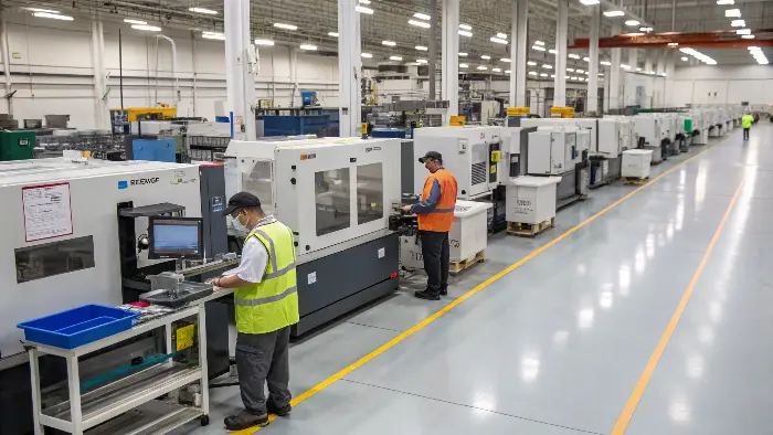
Plan an insert-molding order around three releases: the insert specification, the molded-assembly trial and the production control plan. Agree the evidence and acceptance criteria for each before tooling. The details below identify the design, loading, inspection and supplier records a customer should request.
Insert molding combines a pre-placed component with injected plastic, so the project has two manufacturing systems inside one mold. Success depends on insert design, positioning, heating, material compatibility, operator or automation method and molding stability.
Related CKMOLD resources: injection mold services, DFM analysis, mold design, insert molding and overmolding, and mold testing and validation.
For a CKMOLD enquiry, provide the part and insert drawings, exact resin and insert specifications, volume, functional requirements and acceptance conditions. Confirm the agreed scope for DFM, tooling, loading, trials and production control in the quotation; this article describes review requirements rather than evidence that a particular cell has been validated.
Scope of this guide: This article follows project control from insert specification and DFM through tooling, trial evidence and production release. For geometry rules at the insert–plastic interface, see design considerations for reliable insert-molded products.
What’s the Crucial First Step When We Start an Insert Molding Project?
Before the design review, identify which dimensions and functions depend on the insert, what can damage it during molding, and how a failed assembly will be detected. These inputs determine the review and trial scope.
Review the part and insert drawings together with resin grade, insert surface condition, intended loads and service environment. Resolve conflicting datums, tolerances or acceptance criteria before authorizing tooling.
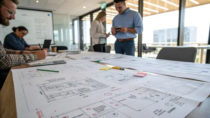
When a project team brings an insert molding project to us, the first thing we do isn’t just look at the CAD files. We talk. We ask a lot of questions. What is this part for? What kind of stresses will it endure? What environment will it operate in? Understanding the end-use is paramount.
Understanding the Core Requirements
We focus on a few key areas during this initial phase:
- Insert Design and Material: Is the insert designed for easy and secure placement in the mold? Are the insert material and the overmolding plastic compatible? Sometimes, a small tweak to an insert’s design, like adding a feature for better grip, can make a huge difference.
- Part Design for Manufacturability (DFM): We look at wall thicknesses around the insert, gate locations, and potential for issues like sink marks or voids. For example, if an insert is quite large, we need to ensure the plastic flow around it is optimal to prevent weld lines in critical areas.
- Tolerances:Tight tolerances are often a feature of insert molded parts. We need to understand what’s critical and what’s not, to balance precision with manufacturing feasibility. Agree critical tolerances and inspection before quoting; any savings require a project-specific comparison.
This detailed upfront work helps us anticipate problems before they even reach the mold-making stage. It’s about setting the project up for success from day one.
How Should the Mold Locate and Support the Insert?
Select locating pockets, pins and supports from the insert’s datums and load path. Check thermal expansion, resin shrinkage, shutoffs and flow-front loading together. Magnetic assistance applies only to a verified responsive material and qualified temperature/load range; it does not replace the required mechanical support.
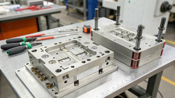
Designing a mold for insert molding is more complex than for a standard injection mold. The mold doesn’t just shape the plastic; it also has to accurately locate and hold the insert(s) against the forces of molten plastic injection.
Key Mold Design Considerations for Inserts
Here’s how we approach it:
- Insert Location and Retention:
- Manual vs. Automated Loading: Compare the complete loading cycle, accessibility, insert presentation, detection, changeover frequency and safe recovery. Specify the selected loading method before freezing the mold layout.
- Holding Mechanisms: Use locating pockets, pins or other suitable features with a defined support path. Qualify any spring or magnetic assistance for the actual insert material, temperature and molding load; ferrous composition alone does not establish magnetic holding performance.
- Preventing Insert Damage: The pressure and temperature of molten plastic can be substantial. The mold must protect delicate inserts. This involves careful gate design to avoid direct impingement of plastic onto sensitive areas of the insert.
- Material Compatibility and Shrinkage:We account for the different thermal expansion rates of the insert material and the overmolding plastic. The mold design needs to accommodate the plastic’s shrinkage around the insert to ensure a tight fit without cracking the plastic or deforming the insert.
Example: Mold Features for Insert Stability
| Feature Type | Description | Acceptance evidence |
|---|---|---|
| Custom Pockets | Precisely machined cavities that match the insert’s shape. | Verify datum position and clearance across the accepted insert tolerance range. |
| Locator Pins | Pins that engage with holes or features on the insert. | Check engagement, support and orientation; rotation control depends on the actual datum geometry. |
| Shut-off Areas | Areas where the mold closes tightly against the insert to prevent flash. | Verify shutoff contact, allowable local load and flash after representative molding trials. |
| Pre-heating/Cooling | Channels in the mold to control the temperature of the insert or surrounding area. | Measure the relevant thermal condition and verify interface performance; preheating is application-specific. |
What Common Hurdles Appear in Insert Molding, and How Do We Tackle Them?
Common hurdles in insert molding include insert shifting or damage, plastic flash, incomplete fill around the insert, and poor adhesion between the insert and plastic. We tackle these by optimizing mold design for secure insert holding, precise process control (injection speed, pressure, temperature), careful material selection, and sometimes pre-treating inserts to enhance bonding.
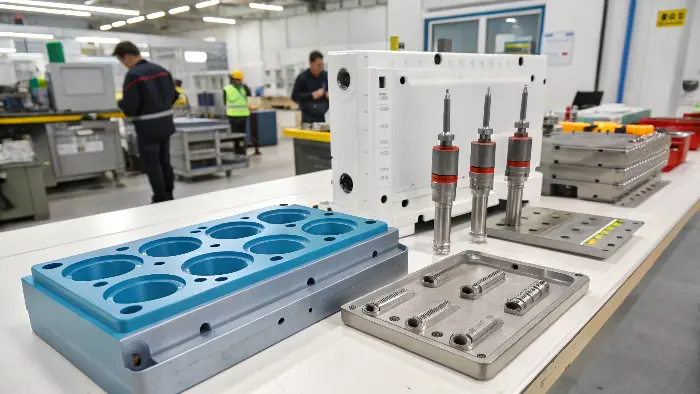
Addressing Key Insert Molding Challenges
Here are some common issues and how we approach them:
- Insert Shifting or Misalignment:
- Cause: Insufficient support in the mold, excessive injection pressure, or insert design not conducive to secure holding.
- Solution: We refine the mold’s holding features (as discussed earlier), adjust injection parameters to be gentler during the initial fill around the insert, and sometimes suggest minor modifications to the insert itself for better stability. For instance, adding a small tab or detent can make a big difference.
- Plastic Flash: Molten plastic seeping into unwanted areas, like seams around the insert.
- Cause: Check insert variation, shutoff contact/support, damage, clamp condition and excessive cavity pressure. Raising clamp force without understanding the local gap can damage the insert or tool.
- Solution: We ensure mold mating surfaces are reliably aligned and that shut-offs around the insert are crisp and precise. Process parameters are also fine-tuned.
- Poor Adhesion/Bonding: The plastic doesn’t stick well to the insert.
- Cause: Material incompatibility, contaminants on the insert surface, or insufficient mechanical interlock.
- Solution: Define whether retention relies on mechanical capture, adhesion or both. If adhesion or sealing is required, validate the exact resin, insert surface and any treatment under the specified service conditions. Chemical affinity is not a universal requirement for a mechanically retained assembly.
- Damage to Inserts: Delicate inserts can be bent, crushed, or broken.
- Cause: High injection pressure directly on the insert, improper handling during loading.
- Solution: Strategic gate placement to avoid direct impact, and careful design of insert loading mechanisms, whether manual or automated.
By systematically diagnosing and addressing these potential issues, often during the DFM and mold design stages, we minimize disruptions during production.
What Evidence Supports Production Release?
Production approval needs a documented control plan, traceable material and insert lots, cavity identification and an agreed reaction to a failed check. Neither a successful trial nor a machine description proves that every later part will meet specification.
Specify which parameters and product characteristics will be monitored, by what equipment, at what frequency and with what acceptance and containment rules. Confirm any proposed automated inspection or real-time monitoring in the project scope and qualification records.
During production, compare current results with the approved process and inspection basis. Include restart, material-lot and cavity checks where the risk assessment requires them; the first accepted part does not establish long-run capability.
Production Control Records
Use the production quality-control guide to define measurement-system suitability, cavity traceability, stability checks and containment responsibilities, then apply those controls to the insert assembly:
- Process Control and Monitoring:
- Record the selected machine, mold and recipe, including relevant temperature, pressure, speed and cooling controls and their permitted ranges. Verify the monitoring and alarm functions required by the control plan.
- Where statistical monitoring is appropriate, define sampling, measurement-system suitability, chart rules and the response to a signal. Use the evidence to assess stability before making capability claims.
- Insert Handling and Loading:
- Choose manual or automated loading from the complete handling cycle, insert presentation, detection, changeovers and fault recovery. Validate missing, reversed, doubled and unseated inserts under an authorized procedure.
- For manual loading, require approved work instructions, operator qualification, seating checks and a safe reaction to a loading fault.
- Quality Inspections:
- First Article Inspection (FAI): Before mass production, a detailed inspection of the initial parts is done to verify all dimensions and requirements.
- In-Process Checks: Regular checks are performed during the production run. This can include visual inspections, dimensional measurements, and functional tests (e.g., pull tests for insert retention).
- Final Inspection: A final quality control check before parts are packaged and shipped.
- Mold Maintenance: Insert molding can sometimes be more demanding on molds due to the interaction with the inserts. Regular cleaning, inspection, and preventative maintenance of the mold are crucial to prevent wear and tear that could affect part quality.
If the insert is stamped sheet metal, review its burr, springback, coating and datum requirements in the sheet-metal hardware DFM guide. Before tool release, define orientation, support, detection and acceptance through the insert loading and retention validation guide.
DFM for Insert Geometry and Plastic Flow
The insert must be shaped so plastic can flow around it, lock mechanically where needed and avoid voids or weak bonding areas. Sharp insert edges, poor undercuts or insufficient plastic thickness can create cracking, flash or weak retention. DFM should review both the insert and the molded plastic.
Positioning and Loading Method
Insert location must be repeatable. Manual loading may be appropriate for lower volume or complex inserts, while automation can improve consistency in higher-volume production. The mold should include features that prevent misloading and protect operators.
Material Compatibility and Thermal Effects
Metal inserts, threaded inserts, magnets and electronic components respond differently to heat and pressure. Thermal expansion, preheating, adhesion, corrosion and overmold stress may need review. The selected plastic should match both functional and processing requirements.
Trial Validation and Production Control
Insert molded parts should be checked for insert position, pull-out strength, flash, voids, cracking, short shots and assembly fit. CKMOLD uses trial feedback to refine insert loading, gate strategy, venting and process settings before production handover.
Insert Molding Project Workflow From Design to Production: Buyer Review Checklist
- Confirm insert material, tolerance and surface condition.
- Design mechanical locking features when bonding alone is not enough.
- Choose manual or automated loading based on volume and consistency needs.
- Prevent insert movement during injection pressure.
- Validate pull-out strength, position and part function after molding.
FAQ
What types of inserts can be molded?
Common inserts include threaded metal inserts, pins, bushings, magnets, contacts and other preformed components, depending on design and material compatibility.
Can CKMOLD support insert molding and overmolding?
Yes. CKMOLD supports insert molding and overmolding project review, mold design, trial validation and production planning.
Use Three Release Gates for an Insert-Molding Order
- Insert release: Approve material, coating, burr limit, datum, dimensional range, cleanliness and storage. Define how incoming inserts are identified and what happens to a nonconforming lot.
- Trial release: Challenge correct, missing and reversed loading under an authorized procedure. Verify detection and the safe reaction before normal cycling. Check insert position, flash, encapsulation, retention and any leak/electrical function required by the drawing.
- Production release: Record insert lot, resin lot, cavity, process and agreed sampling. Define retention-test method, conditioning and reaction to a failed result; one passing pull test is not a complete control plan.
Keep insert retention, polymer adhesion and leak-tightness separate: success in one does not prove the other two. Thermal cycling may load the interface differently from a room-temperature pull test. Protolabs’ insert-molding design guidance is a general design reference; the final insert assembly needs its own evidence.
Include insert drawings, tolerance ranges, loading volume and functional limits in a scoped insert-molding enquiry. Ask the quotation to identify fixture, detection, automation, trials and inspection deliverables explicitly.
Conclusion
Release the order against the approved insert specification, trial record and production control plan. Resolve unclear responsibilities for insert supply, tooling, detection, inspection and change control before approval; keep acceptance tied to the actual assembly and its service conditions.