
Polyethylene (PE) is cheap and versatile, but poor mold design can ruin your production line. You struggle with warping parts, unpredictable shrinkage, and cycle times that eat into your profit margins. These issues create bottlenecks that frustrate your team and delay shipments.
Optimizing mold design for PE plastic parts requires a specific focus on high shrinkage rates, efficient cooling channels, and strategic gating. Because PE is a semi-crystalline material, it shrinks significantly (1.5% to 3.0%) as it cools. To counter this, you must oversize the mold cavities and design cooling systems that dissipate heat evenly. Proper venting is also critical to prevent trapped gas burns. By addressing these thermal behaviors early, you ensure consistent dimensions and faster cycle times.

Many manufacturers treat PE like any other plastic, but that is a costly mistake. I remember when I first started on the factory floor, we assumed a simple "shrink factor" would work for everything. We were wrong. PE has a mind of its own. If you don’t respect its properties, you will end up with thousands of rejected parts. Let’s dig into the specific strategies that will save your production schedule.
Why Is Handling Shrinkage the Biggest Challenge in PE Mold Design?
Every mold maker knows plastic shrinks, but PE shrinks more than most, causing massive headaches for precision parts. You design a part to be 100mm, but it comes out of the mold at 97mm, and suddenly your assembly line stops. This unpredictability creates waste and forces expensive tooling modifications.
To handle PE shrinkage effectively, you must calculate shrinkage based on density and flow direction, not just a general average. PE is semi-crystalline, meaning its molecular chains pack tightly as they cool, leading to high shrinkage rates between 1.5% and 3.0%. High-density polyethylene (HDPE) shrinks more than Low-density polyethylene (LDPE). Furthermore, shrinkage is often higher in the direction of flow than across it. You need to apply differential shrinkage factors to your CAD models before cutting any steel.

Let’s break this down further because this is where most projects fail. Shrinkage isn’t just one number you plug into a computer. It is a dynamic behavior influenced by processing conditions. When I work with clients, I always emphasize that "steel safe" is the only safe way to proceed.
Here is how I approach the shrinkage problem for PE:
Understanding the Variables
You cannot guess. You have to look at the specific grade of PE you are using.
- Density Matters: HDPE packs tighter than LDPE. Tighter packing means more volume reduction.
- Cooling Rate: Fast cooling "freezes" the amorphous structure, reducing shrinkage slightly but increasing internal stress. Slow cooling allows crystals to form, increasing shrinkage.
Strategies for Dimensional Control
If you want your parts to fit together, you need a plan.
| Factor | Effect on PE Shrinkage | Design Solution |
|---|---|---|
| Flow Direction | Molecules align with flow, causing more shrink in that direction. | Adjust cavity dimensions differently for length vs. width. |
| Wall Thickness | Thicker walls hold heat longer, allowing more crystallization and shrink. | Core out thick sections to maintain uniform wall thickness. |
| Packing Pressure | Higher pressure forces more material in, reducing shrink. | Ensure gates are large enough to transmit pressure before freezing. |
When I was running my first independent project, I had a lid for a container that kept warping. We realized the shrinkage was different in the center compared to the edges because of the flow pattern. We had to modify the mold to "pre-warp" the cavity in the opposite direction. It looked wrong in the steel, but the part came out perfectly flat.
How Does Cooling System Design Impact Cycle Time and Warpage?
You want to run your machines as fast as possible, but if you eject PE parts too hot, they warp instantly. Poor cooling is the number one cause of long cycle times and distorted products. You end up waiting for the part to cool while your machine sits idle, costing you money every second.
The cooling system for PE molds must be aggressive and uniform, utilizing conformal cooling or highly conductive alloys like Beryllium Copper in hot spots. Since PE has a high specific heat, it holds onto energy. You need cooling channels placed close to the cavity surface (typically 1-2 diameters away) and spaced closely together. Uneven cooling causes differential shrinkage, which pulls the part out of shape. Efficient heat removal is the key to flat parts and fast cycles.

I often see molds where the cooling lines are just drilled wherever there is empty space. That is lazy design. In my experience, the cooling system is actually more important than the ejection system for PE.
The Thermal Conductivity Challenge
PE is an insulator. It resists giving up its heat. This means your mold steel needs to do the heavy lifting.
- Standard Steel (P20): It is okay for general use, but for high-speed PE production, it might be too slow.
- Beryllium Copper (BeCu): We insert this into corners or deep cores. It transfers heat 5 to 10 times faster than steel.
Cooling Layout Best Practices
You need to think about where the heat is trapped.
- Uniformity is King: If one side of the part is 50°C and the other is 30°C, the part will bow towards the hotter side.
- Turbulent Flow: You need water moving fast. We aim for a Reynolds number over 4000 to ensure the water scrubs the heat off the channel walls.
- Baffles and Bubblers: For deep cores (like inside a bottle cap or a deep housing), simple drilled lines won’t reach. We use bubblers to shoot water up into the tip of the core and back down.
One of my clients, Michael, had a crate mold that was taking 60 seconds to cycle. The bottom was warping. We redesigned the core cooling to use a spiral baffle system. We dropped the cycle time to 45 seconds and the warping vanished. That 15-second saving per part added up to huge savings over the year.
What Are the Best Gating Strategies for Polyethylene?
Choosing the wrong gate type or location creates ugly weld lines, weak points, and surface defects. You might see "splay" marks near the entry point or parts that break easily under stress. If the gate is too small, you cannot pack the mold properly; if it is too big, you have a manual trimming nightmare.
For PE parts, you should prioritize gates that allow for high volume flow without high shear, such as edge gates or direct sprue gates for larger parts. PE is shear-sensitive; excessive shear heat can degrade the material. Hot runner systems are excellent for PE to eliminate waste, but temperature control is vital to prevent "drooling" or stringing. The gate location must be placed to fill the thickest sections first, ensuring proper packing pressure travels through the part as it cools.

The gate is the doorway for the plastic. If the door is too small, you can’t get the furniture in. If the door is in the wrong spot, you ruin the flow of the room.
Selecting the Right Gate Type
- Edge Gate: Standard and reliable. Good for flat parts. It leaves a mark on the side that needs trimming.
- Submarine (Tunnel) Gate: Great for automatic degating. The part shears off the runner upon ejection. We use this a lot for high-volume small PE parts.
- Hot Tip: Essential for high-volume production. It eliminates the runner (waste). However, PE can "string" (leave a thin hair of plastic) if the tip temperature isn’t perfectly controlled.
Location Strategy
Where you put the gate determines the molecular orientation.
- Fill Thick to Thin: Always gate into the thickest area. This allows you to push plastic into the shrinking areas as they cool. If you gate thin-to-thick, the thin gate freezes off first, and the thick part shrinks and creates a sink mark (a dimple).
- Hiding the Mark: Discuss with your design team where the "show surface" is. Never put a gate on a cosmetic surface unless absolutely necessary.
- Venting Awareness: The air inside the mold has to leave as the plastic enters. Place gates so that the plastic pushes air towards the vents, not into a trapped corner where it will burn the plastic (diesel effect).
I once troubleshot a project for a toy manufacturer. The PE parts were snapping at the hinge. We looked at the flow and realized the gate was placed so that a weld line (where two flow fronts meet) formed right at the hinge. We moved the gate to the center, eliminating the weld line, and the part became unbreakable.
How Can You Prevent Common Surface Defects in PE Molding?
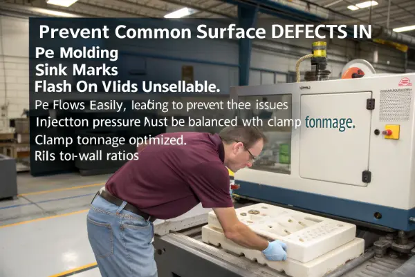
Even with good dimensions, surface defects like sink marks, flash, or voids can make your product unsellable. PE flows easily, which is good, but it also means it flashes easily into tiny gaps. Conversely, its high shrinkage leads to sink marks on the surface opposite any internal ribs or bosses.
To prevent surface defects in PE, you must balance injection pressure with clamp tonnage and optimize rib-to-wall ratios. Sink marks occur when internal features are too thick; a general rule is that rib thickness should be 50-60% of the main wall thickness. To prevent flash, the mold parting lines must be precision-machined and robust enough to withstand injection pressure without opening. Texturing the mold surface can also help hide minor sink marks and scuffs.

Surface finish is often the first thing the customer notices. If it looks cheap or defective, it doesn’t matter how strong it is.
Fighting Sink Marks
PE loves to shrink, pulling the surface in.
- The 60% Rule: If your main wall is 3mm, your supporting ribs shouldn’t be thicker than 1.8mm at the base. If they are too thick, the mass of plastic there stays hot, shrinks, and pulls the surface down.
- Coring Out: Remove unnecessary material. Use gussets for strength instead of solid blocks of plastic.
Preventing Flash
Flash is that thin, sharp excess plastic on the edges.
- Precision Spotting: The two halves of the mold (core and cavity) must fit together perfectly. I call this the "blue match" process. We use blue dye to check the seal.
- Clamp Force: PE is runny. If your machine doesn’t squeeze the mold shut hard enough, the pressure of the plastic will force it open just a hair—enough for flash to shoot out.
- Vent Depths: You need vents for air, but if they are too deep (over 0.02mm for PE), plastic will flow into them.
Surface Textures
This is a "secret weapon" for PE. Since PE is soft and scratches easily, a high-gloss finish often looks bad after shipping.
- Texture Hides Sins: A light matte texture or grain can hide sink marks and flow lines.
- Draft Angles: If you add texture, you must increase the draft angle (the slope of the walls) so the part doesn’t drag on the texture when ejecting. Usually, add 1 to 1.5 degrees of draft per 0.025mm of texture depth.
I always advise clients like Michael to look at the "A-surface" critical areas. We can often save a tool design by just thinning out a rib slightly or adding a subtle texture, rather than rebuilding the whole cooling system.
Conclusion
Optimizing mold design for PE requires a deep respect for the material’s high shrinkage and thermal properties. By calculating precise shrinkage rates, designing aggressive cooling systems, choosing the correct gating, and managing wall thickness to prevent defects, you can achieve high-speed, high-quality production. It is not just about cutting steel; it is about understanding how the plastic behaves inside that steel. At CKMOLD, we apply these principles daily to ensure our clients succeed.