
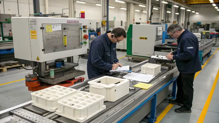
It is frustrating when your well-crafted injection molded products emerge with defects. These defects are unproductive and pure waste of time, material and money and figuring out the exact root of the problem can sometimes seem like a complicated detective process. Unless you detect and correct the problem, you will only continue to produce bad parts which no designer or producer will desire.
Injection mold defects should be analyzed as evidence of a system condition, not as a reason to change settings randomly. Short shots, flash, sink, burn, flow marks, warpage, sticking and dimensional drift can originate in the material, machine, mold, process, measurement or handling. A structured investigation narrows the cause and creates a correction that can be verified and maintained.
Related CKMOLD resources: mold testing and validation, mold repair or modification, production injection molding.
In order to diagnose injection mold defects, first clearly identify the defect. Then, in a systematic fashion, examine the mold design, the process conditions (e.g., temperature, pressure, and speed), and the plastic material properties in use. Test techniques, like microscopy or material analysis, can be used to find the cause. Finally, take corrective and preventive measures to prevent repetition of the defect.

What are the defects in injection molding?
You’ve spent hours, maybe days, perfecting your product design, only to find the first molded samples are riddled with issues. These imperfections, from small blemishes to major distortions, can ruin the part’s look, its function, or both. Correctly identifying what type of defect you’re seeing is the very first step towards a solution, because different defects point to different underlying problems.
Some of the most prevalent injection molding defects include sink marks, warping, flash, short shots, burn marks, weld lines and voids. They all appear differently and typically signal potential defects in the mold itself, the moldable plastic, or the machine processing conditions. Detection of these specific defects is the principle of successful troubleshooting..

Fast defect recognition is useful, but visual pattern recognition is only a starting hypothesis. Record the defect, cavity, material, process and measurement condition before selecting a cause or changing the mold.
Here’s a rundown of some frequent issues:
- Sink Marks: Dimples or depressions on the surface of the molded part. They will form on the backside surface of ribs or bosses, or in thicker part sections. The main cause is likely to be insufficient packing pressure while cooling, or uneven cooling where thicker sections contract more after the outer skin has hardened.
- Warping: When the component becomes distorted or bent from its initial form as it cools. It is primarily caused by differential shrinkage rates of the component due to non-uniform wall thickness, non-uniform mold cooling, or stresses caused by ejection.
- Flash: Flash is a light plastic excess that escapes from the mold cavity, usually along the parting line, or around ejector and core pins. It is usually a sign that the mold halves are not closing tight enough, injection pressure is set too high, or the mold is worn or damaged.
- Short Shot: This defect occurs when molten plastic fails to fill the mold cavity and therefore results in an incomplete part. This typically occurs due to injecting too little material, injection pressure or speed being too low, or blocked gates or runners.
- Burn Marks: These are brown or black discolored zones, typically at the end of the material flow path or in under-vented areas. They are the result of trapped air overheat by high-rate compression (e.g., a diesel engine effect) or by the plastic material itself being degraded due to high temperature or shear.
- Weld Lines (Knit Lines): These are lines or notches formed where two or more flow fronts of melted plastic cross and merge. If the melt fronts were too cold prior to their meeting, the weld will be poor, and this can result in a cosmetic flaw or a structural weak point.
Here’s a quick table summarizing these:
| Defect | Appearance | Common General Causes |
|---|---|---|
| Sink Marks | Surface depressions, dimples | Insufficient packing, uneven cooling, thick sections |
| Warping | Distortion from intended shape | Differential shrinkage, non-uniform cooling, internal stress |
| Flash | Thin excess material at parting line/pins | Low clamp force, high injection pressure, mold wear |
| Short Shot | Incomplete part, cavity not fully filled | Insufficient material, low pressure/speed, blocked gates |
| Burn Marks | Black/brown scorches | Trapped air, material degradation, excessive temperature |
| Weld Lines | Visible line where flow fronts meet | Melt fronts cooling too much before fusing, poor flow path |
This isn’t an exhaustive list, but it covers many of the common headaches that designers and molders face. Recognizing them is the first step to a cure.
Move From Triage to Root-Cause Proof
Root-cause analysis begins after containment and a repeatable defect definition. Preserve suspect and known-good samples, cavity/lot/time identity and machine traces. Then map possible causes across material, machine, mold, method, measurement and environment.
- Describe the defect with location, direction, magnitude, cavity and frequency.
- Establish when it entered the process and which conditions changed.
- Rank mechanisms that explain the complete pattern—not only one symptom.
- Run a controlled test that can disprove each leading hypothesis.
- Verify the correction across the approved process window and repeat production.
- Update controls, maintenance or design so the cause does not recur.
Use the separate problem-triage guide for initial classification; this article covers cause confirmation and recurrence control.
If the symptom is a flow-front meeting line, use the dedicated weld-line evidence and risk guide before changing gate or process conditions.
For visible bands that may be flow lines or jetting, follow the flow-line location and process guide before selecting a correction.

Prove Whether the Burn Is Compressed Gas or Material Degradation
A dark mark at an end-of-fill pocket can result from compressed trapped gas, while streaks or deposits may reflect excessive residence, temperature, shear or contamination. Location, odor, cavity pattern, purge condition, vent history and process traces help separate them.
For a gas-trap hypothesis, inspect and measure the actual vent path, cleanliness, land and exit; vent dimensions must suit the exact resin and flash limit rather than a universal 0.01–0.05 mm range. For degradation, review resin/lot, drying where required, barrel/nozzle temperature, residence, screw recovery and dead spots.
Verify the correction with repeated samples and confirm that added venting or changed speed does not introduce flash, weld or appearance issues.

What are the causes of sink marks, and what are the prevention and correction strategies for sink marks in injection molding?
Sink Marks
Sink marks are surface depressions or indentations of injection-molded components, usually in thicker regions where the outer case cools and solidifies before the inner material.
Sink marks are basically empty spaces that are created because of the lack of pressure within the mold cavity while cooling and solidifying. Sink marks occur more readily in designs containing different wall thicknesses.
Common Causes of Sink Marks
The main reason for sink marks is the difference in cooling rate between the thicker and the thinner part sections. Lack of pressure during the pack stage of the injection molding process also causes this defect.
Prevention and Correction Strategies
Prevent sink marks by maintaining even wall thickness throughout the part design. A change in the holding pressure and time also has a positive effect, as it offsets the material shrinkage in thicker areas. Further, optimizing the cooling system within the mold to provide even cooling can go a long way in minimizing the occurrence of sink marks.
Trace Contamination Through the Material Path
Identify the contaminant if possible, then trace packaging/opening, drying and conveying, hopper/magnet/filter, barrel/nozzle, hot runner, mold surface, secondary handling and packaging. Compare color/grade change history and purging. A particle may be degraded resin, foreign polymer, metal, oil, dust or external handling debris; each needs a different corrective action.
Retain samples, lot numbers and cleaning records. If regrind is permitted, define source, percentage, separation, contamination control and test evidence. Do not assume regrind is the cause or that it is acceptable for every product.

What Supplier Evidence Reduces Defect Risk?
Supplier claims do not prevent defects. Ask for drawing-linked DFM, material and revision traceability, trial/process records, cavity-level measurements, calibrated inspection, control/reaction plans, nonconformance handling, corrective-action evidence and tool maintenance history appropriate to the project.
Define required evidence in the RFQ before quotation. When a defect occurs, require containment, scope, verified root cause, correction and effectiveness check—not only replacement parts.
Define and Contain the Defect
Record the defect, location, cavity, time, material lot, machine, mold revision, process and inspection condition. Separate suspect parts, preserve samples and prevent unapproved changes from making the baseline disappear. A defect map is more useful than a general statement that the parts look bad.
Use the 5M1E System View
Review material, machine, mold, method, measurement and environment. Check drying, resin grade, screw or check ring, pressure, temperature, gate, vent, cooling, ejection, gauge, fixture, ambient and operator handling. This prevents the investigation from assuming every problem is a mold problem.
Look for Cavity, Direction and Timing Patterns
A single cavity suggests local gate, vent, insert, cooling or wear risk. A flow-direction pattern suggests gate, orientation or shrinkage. A time-after-ejection change suggests cooling or residual stress. A shift after maintenance or material change gives another valuable clue.
Run Controlled Tests
Use short shots, cavity comparisons, material verification, gauge checks, cooling-flow checks or one-variable trials. Record the response and repeat the best condition. If the defect does not respond to a reasonable process window, inspect or modify the mold rather than increasing settings indefinitely.
Close With Corrective Action and Prevention
Document root cause, correction, owner, verification, process update and maintenance trigger. Add a check to prevent recurrence, such as vent cleaning, material-drying confirmation, cavity inspection, gauge calibration or revision approval.
Analyze the Root Cause of Injection Mold Defects: Buyer Review Checklist
- Contain the issue, preserve baseline samples and record cavity, location, timing and condition.
- Review material, machine, mold, method, measurement and environment systematically.
- Use cavity, flow direction, time-after-ejection and maintenance patterns to narrow the cause.
- Run controlled tests and repeat the corrected condition before changing steel or process.
- Document corrective action, verification, process update and recurrence-prevention trigger.
FAQ
What should be checked first when a mold defect appears?
Contain the issue and record the exact defect, cavity, material, machine, process, mold revision and measurement condition before making changes.
How do I know whether a defect is caused by the mold or machine?
Compare cavities and runs, verify material and measurement, check process traces and perform controlled tests that isolate mold, machine and material variables.
Conclusion
Injection-molding defect analysis should end with a demonstrated mechanism, verified correction and recurrence control. Record what changed, repeat the approved condition and update the relevant process, maintenance, inspection or design control.