
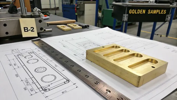
Choose an SPI mold finish by specifying the tool-surface preparation, the required appearance on the molded part and an acceptance method. The A, B, C and D designations are useful purchasing shorthand, but they do not guarantee the same plastic gloss or roughness on every resin, color, geometry or molding process. Treat the finish as a zoned engineering requirement, then approve it on representative molded samples.
The table below follows the DME Micro-Finish Mold & Tool Finish Guide. DME labels the values as approximate resulting Ra for the stated preparation guideline. They are not universal tolerances for every polishing supplier or a guarantee of the molded part surface.
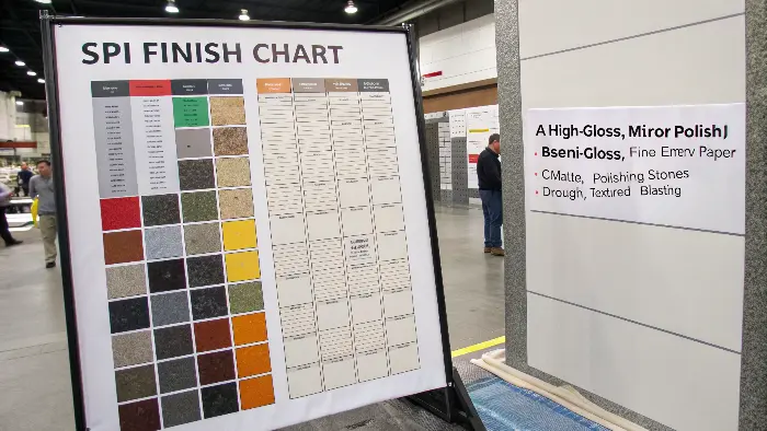
DME SPI finish chart: method and approximate mold-surface Ra
| Designation | DME preparation guideline | Approx. Ra in microinches | Approx. Ra in µm |
|---|---|---|---|
| A-1 | Grade #3 diamond buff | 0–1 | 0–0.025 |
| A-2 | Grade #6 diamond buff | 1–2 | 0.025–0.051 |
| A-3 | Grade #15 diamond buff | 2–3 | 0.051–0.076 |
| B-1 | 600-grit paper | 2–3 | 0.051–0.076 |
| B-2 | 400-grit paper | 4–5 | 0.102–0.127 |
| B-3 | 320-grit paper | 9–10 | 0.229–0.254 |
| C-1 | 600 stone | 10–12 | 0.254–0.305 |
| C-2 | 400 stone | 25–28 | 0.635–0.711 |
| C-3 | 320 stone | 38–42 | 0.965–1.067 |
| D-1 | Dry blast, glass bead #11; 8-inch distance, 100 psi, 5 seconds | 10–12 | 0.254–0.305 |
| D-2 | Dry blast, #240 oxide; 5-inch distance, 100 psi, 6 seconds | 26–32 | 0.660–0.813 |
| D-3 | Dry blast, #24 oxide; 6-inch distance, 100 psi, 5 seconds | 190–230 | 4.826–5.842 |
Unit note: DME publishes Ra in microinches. The µm column is a mathematical conversion using 1 microinch = 0.0254 µm and is rounded. DME’s blast media, distance, pressure and time are part of its stated D-grade preparation conditions. Changing the equipment, media condition, angle, steel, operator technique or exposure can change the result.
For process planning beyond the finish chart, review the controlled mold-polishing stages, the polishing-tool selection guide and the steel-preparation-to-optical-finish workflow. Each addresses a different purchasing or execution decision.
What A, B, C and D actually describe
- A finishes use diamond buffing for highly polished tool surfaces. Whether the part appears mirror-like depends on the steel, resin and molding process as well as the polish.
- B finishes use abrasive paper and normally leave controlled linear preparation marks. Drawing direction and transition between zones should be agreed.
- C finishes use stones and create a less reflective tool surface. They may be appropriate where a high gloss is not required, but they are not a substitute for a defined visual sample.
- D finishes use dry blasting under stated conditions. D-1 is glass bead #11, D-2 is #240 oxide and D-3 is #24 oxide in the DME guide. These are not interchangeable descriptions.
An SPI/DME finish designation describes preparation of the mold surface. It is different from a proprietary chemically etched or laser-applied texture code. A custom texture normally has its own depth, pattern, draft, grain direction, repair and approval requirements.
The mold surface is not the molded-part result
A profilometer can measure the steel surface, but the customer normally accepts the plastic part. Replication is affected by:
- resin family, grade, hardness and shrinkage;
- glass, mineral or other fillers;
- colorant, masterbatch and gloss modifiers;
- part thickness, ribs, bosses and transitions;
- gate location, flow direction and weld lines;
- melt and mold temperature, packing, cooling and venting;
- release behavior, draft and ejection;
- tool steel, polishing quality, contamination and wear.
For that reason, “A-2” should not be translated into a universal molded-part gloss number, and an Ra value on steel should not be presented as the plastic-part Ra without an agreed correlation. TPE and TPU are also not universally excluded from high-gloss applications: the achievable appearance depends on the specific grade, hardness, color, tool surface, geometry and process. Approve the actual resin and color on a representative sample.
Choose the finish by part function and viewing zone
| Part requirement | Useful starting discussion | Risk to control |
|---|---|---|
| Optical or high-gloss appearance | Review an A-family polished tool surface with the specified steel, resin and color. | Polish defects, inclusions, flow marks, weld lines and geometry can remain visible even when the tool meets a preparation callout. |
| Controlled satin or low-gloss appearance | Evaluate B, C or a qualified texture sample rather than choosing solely by grade name. | Different processes can produce similar average Ra but visibly different directionality and gloss. |
| Grip, fingerprint management or decorative grain | Use a texture supplier’s pattern and depth specification with a molded plaque or boundary sample. | Texture depth affects release and repair; insufficient draft can scuff the part. |
| Sealing, sliding or optical interface | Specify the functional surface separately, including measurement and permitted defects. | A decorative finish may interfere with sealing, friction, light transmission or dimensional contact. |
| Hidden, non-cosmetic area | Use the least complex finish that still supports release, cleaning and tool maintenance. | Unnecessary polishing adds cost and can round edges or alter critical geometry. |
Polish and texture do not correct molding defects
A coarser or blasted surface can make some visual features less noticeable under certain lighting, but it does not remove sink, weld-line weakness, burn marks, poor venting, flow imbalance or dimensional error. Those problems require DFM and process correction. Texture should be chosen for the intended appearance or function, not used as an undocumented way to conceal a defect.
Likewise, calling for an A-grade polish does not create optical quality if the tool steel, EDM preparation, part geometry or resin is unsuitable. Review the finish together with the mold-steel selection and the molding conditions.
What drives finish cost and lead time
There is no defensible rule that one SPI grade always adds a fixed number of hours or a fixed percentage to the mold price. Cost depends on the starting surface, polished area, accessibility, steel cleanliness and hardness, geometry, required edge protection, zoned transitions, measurement method, sample iterations and repair risk.
To control cost:
- apply the demanding finish only to the zones that need it;
- mark finish boundaries and draw direction on the 2D drawing;
- avoid deep narrow areas that cannot be polished consistently;
- select steel and heat treatment that support the finish;
- approve a resin-and-color sample before final tool acceptance;
- define who owns texture application, repair and re-approval.
Surface-finish requirement checklist for an RFQ
- Specified area: drawing zones, boundaries, parting-line treatment and excluded functional surfaces.
- Appearance objective: gloss, satin, grain, optical clarity, tactile feel, fingerprint or glare requirement.
- Material: exact resin grade, filler, color and masterbatch.
- Reference: DME/SPI preparation designation, texture supplier code, physical plaque or approved production sample.
- Viewing conditions: distance, angle, illumination, background and whether the part is assembled.
- Measurement: steel Ra, part Ra, gloss, color or visual boundary sample; include instrument, cut-off, direction and sampling locations when numerical inspection is required.
- Acceptance boundary: permitted scratches, waviness, flow marks, weld lines, gate vestige and zone-to-zone variation.
- Release and draft: texture depth, draw direction, shutoffs and draft approved by the texture provider and mold designer.
- Maintenance: cleaning method, repair blending and the process for re-approving a repaired surface.
How to approve the finish before production
First, agree the tool-surface process and the part-level acceptance criteria. Next, review the finish during mold design so that draft, gates, vents and access are compatible. At trial, mold the specified production resin and color within a documented process window. Inspect samples under the agreed conditions and retain signed boundary samples for future comparison. Include the result in the mold testing and validation file.
Use the injection mold cost estimator only for a preliminary tooling budget. Finish area, polish route, texture ownership and acceptance method still need an engineering quotation. To review those requirements with the part data, request an engineering review.